Transmission Assemble
Transmission Assemble
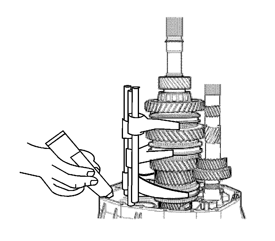
1. Clean the gasket surface and apply sealant.
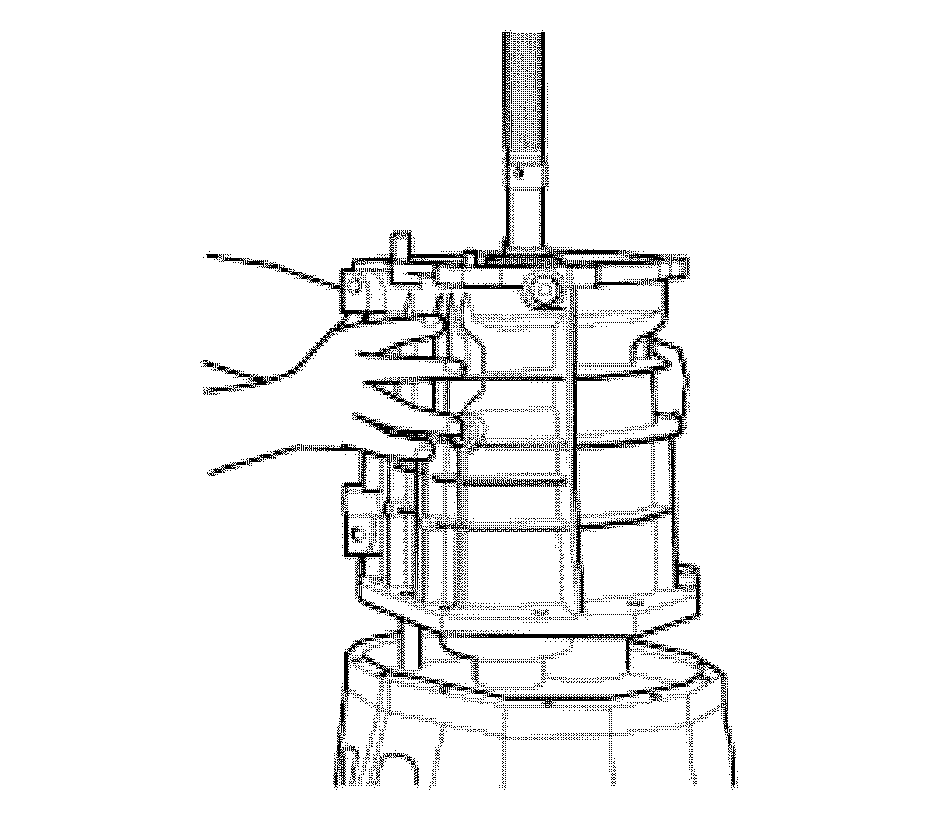
2. Install the casing.
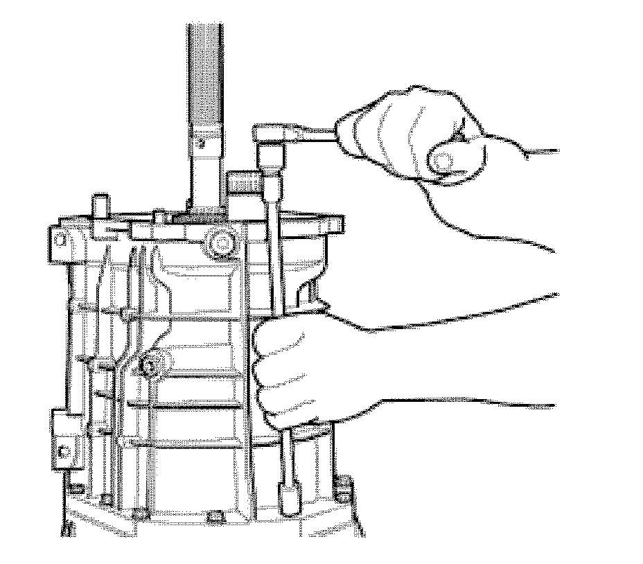
Notice: Refer to Fastener Notice .
3. Using a 10 mm wrench, install the 14 screws that secure the casing.
4. Tighten the screws.
Tighten the screws to 24-37 N.m (18-28 lb ft.)
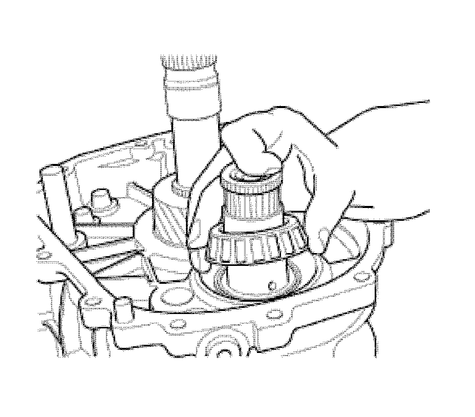
5. Install the bearing cone.
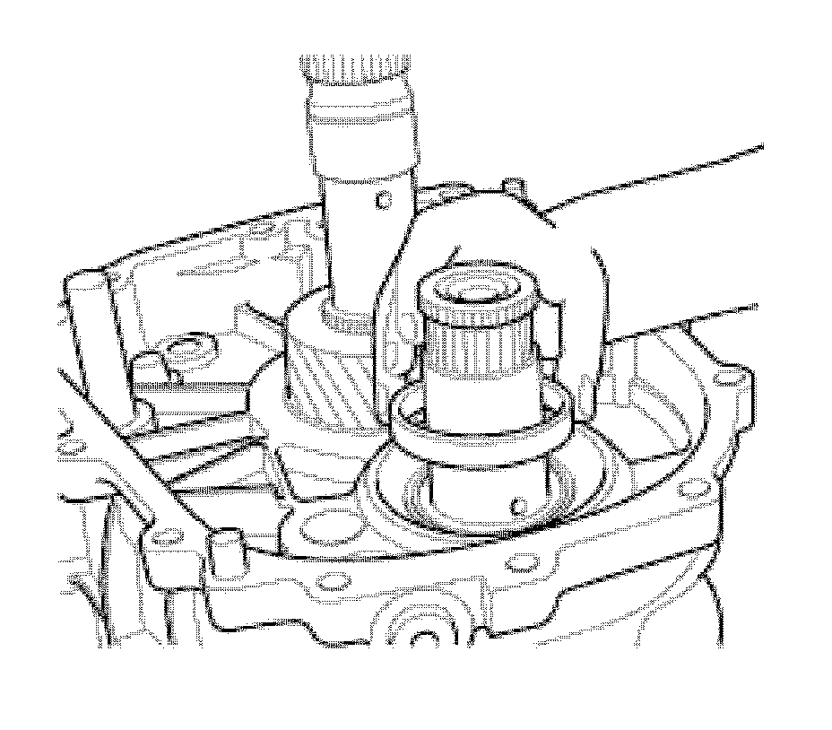
6. Install the gear train taper bearing cup.
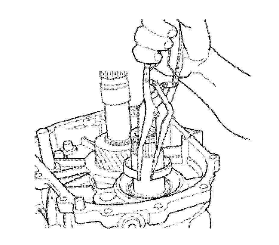
7. Using retainer pliers, install the retainer securing the gear train bearing race.
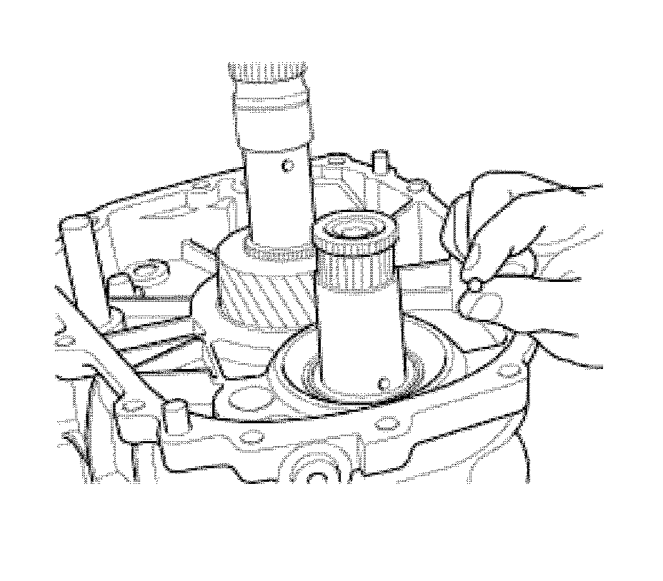
8. Install the drag ball.
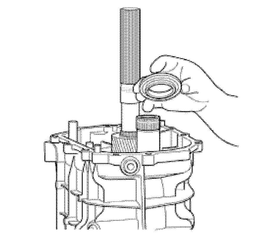
9. Install the drive wheel.
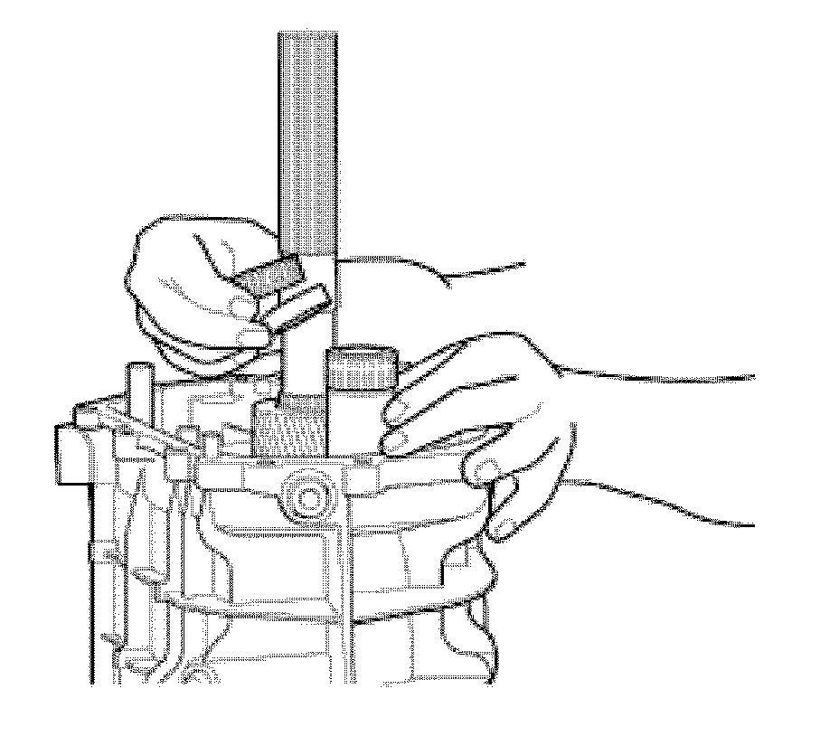
10. Install the 2 roller bearings and spacer.
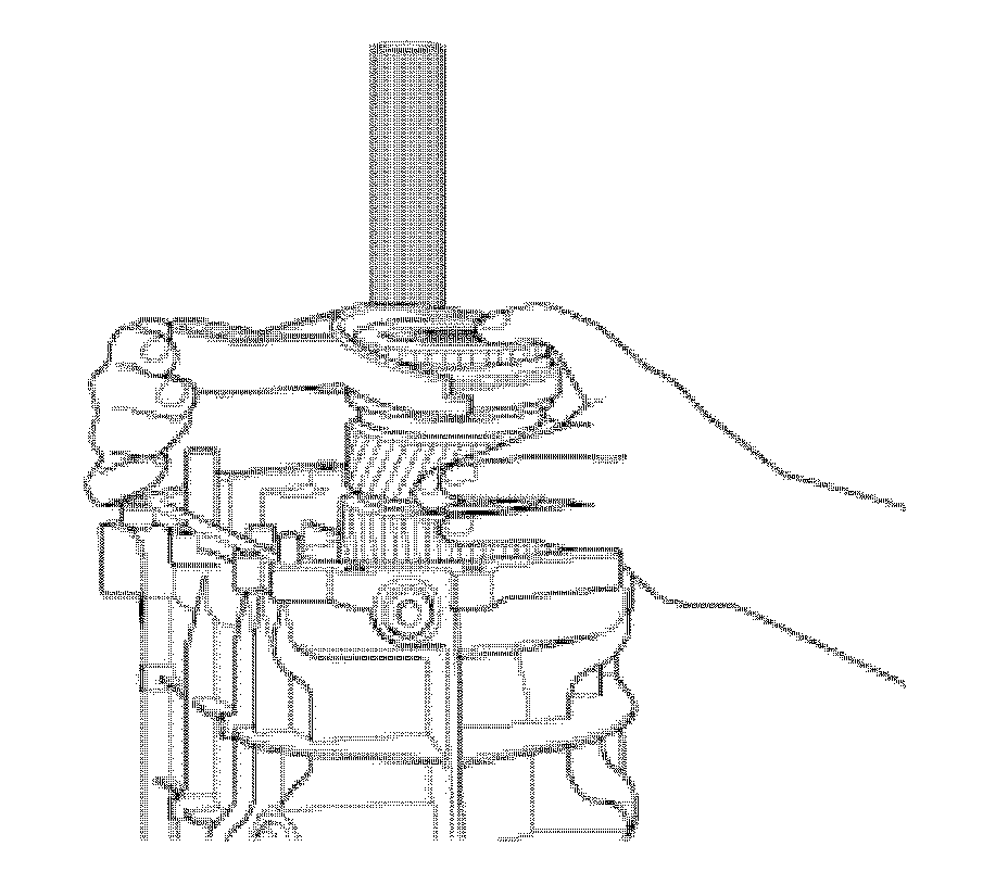
11. Install the 5th speed synchronizer assembly next to the fork.
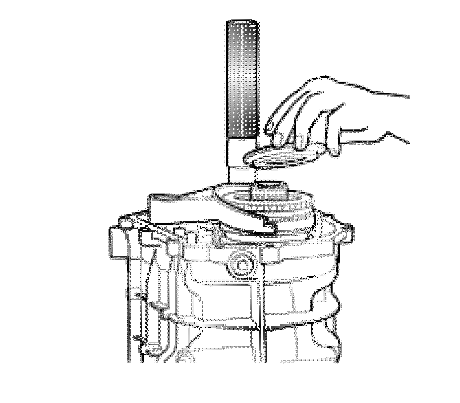
12. Install the synchronizer ring.
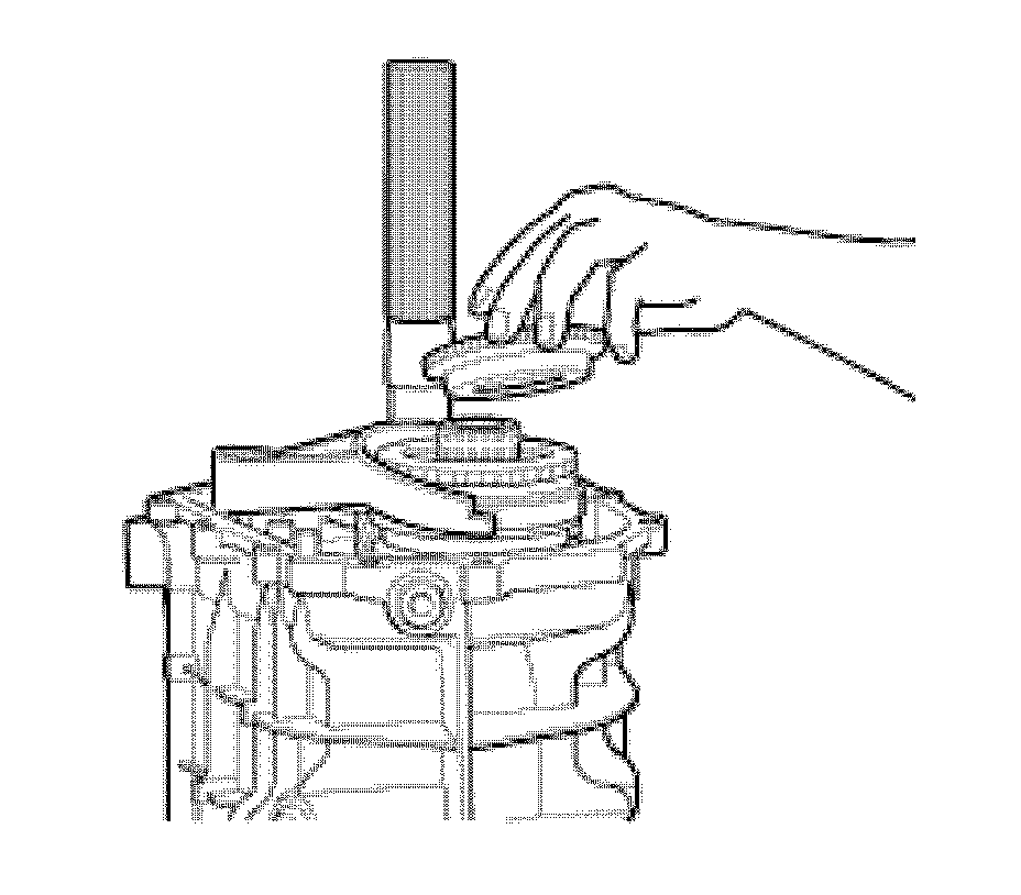
13. Install the 5th speed synchronizer assembly coupling cone.
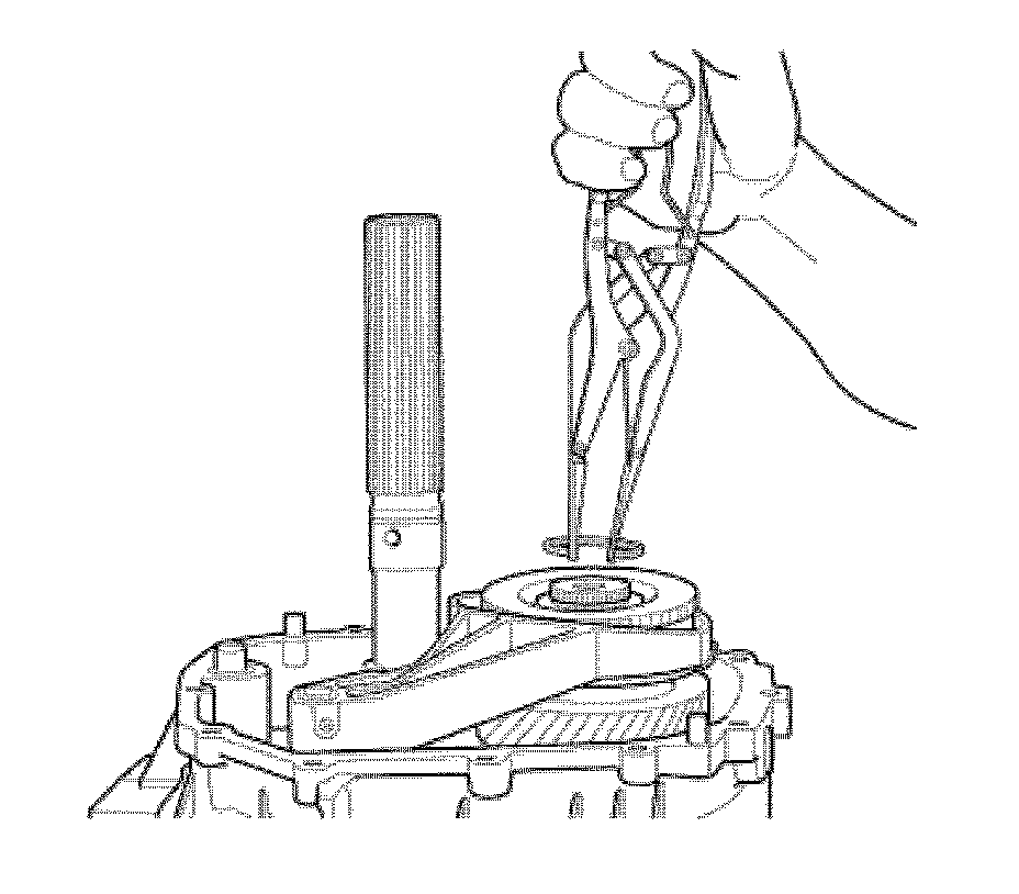
14. Using retainer pliers, install the gear train 5th speed gear retainer.
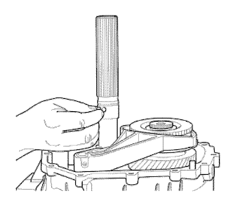
15. Install the speedometer drag ball.
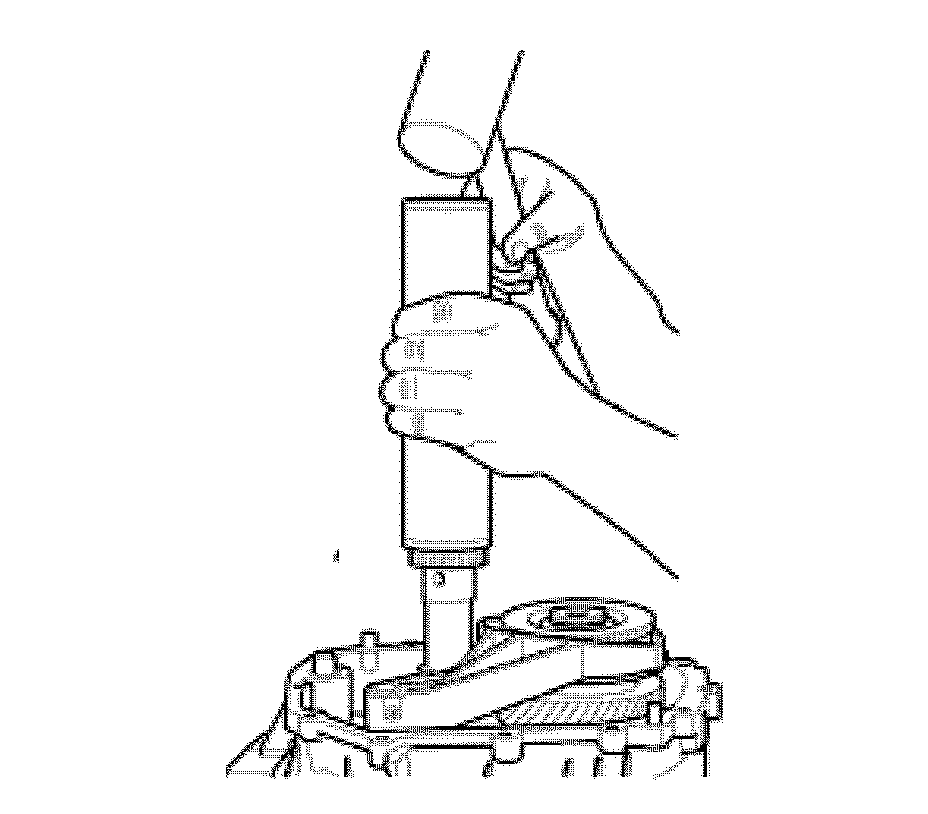
16. Using a driving tool, install the speedometer gear.
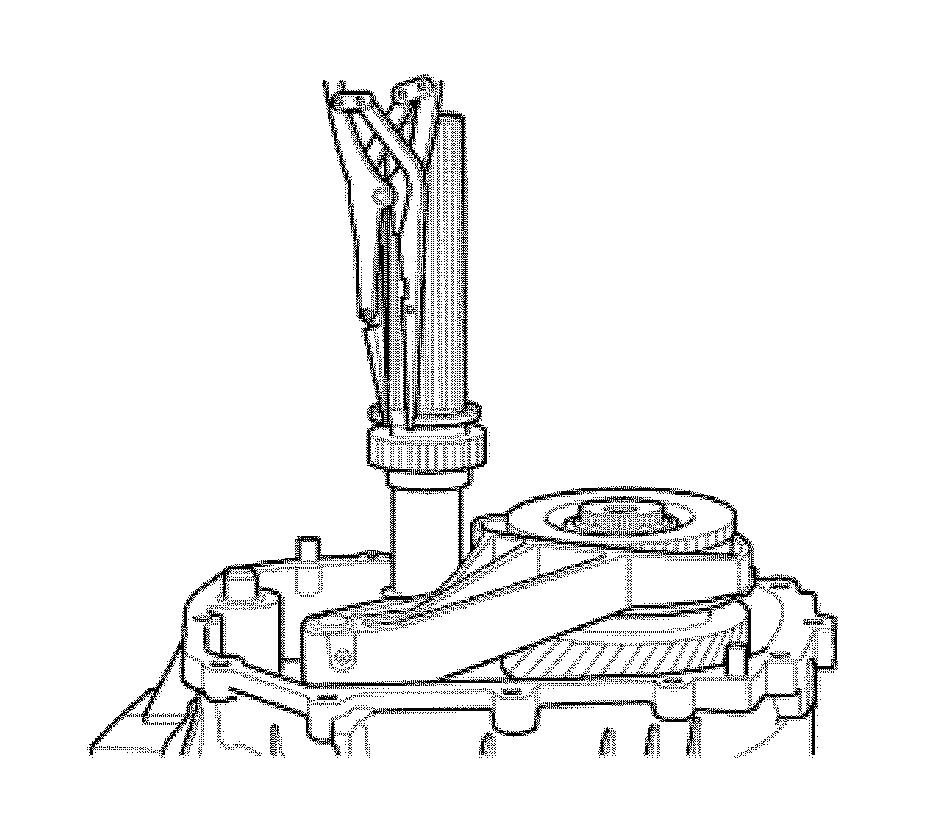
17. Using retainer pliers, install the retainer that secures the speedometer gear.
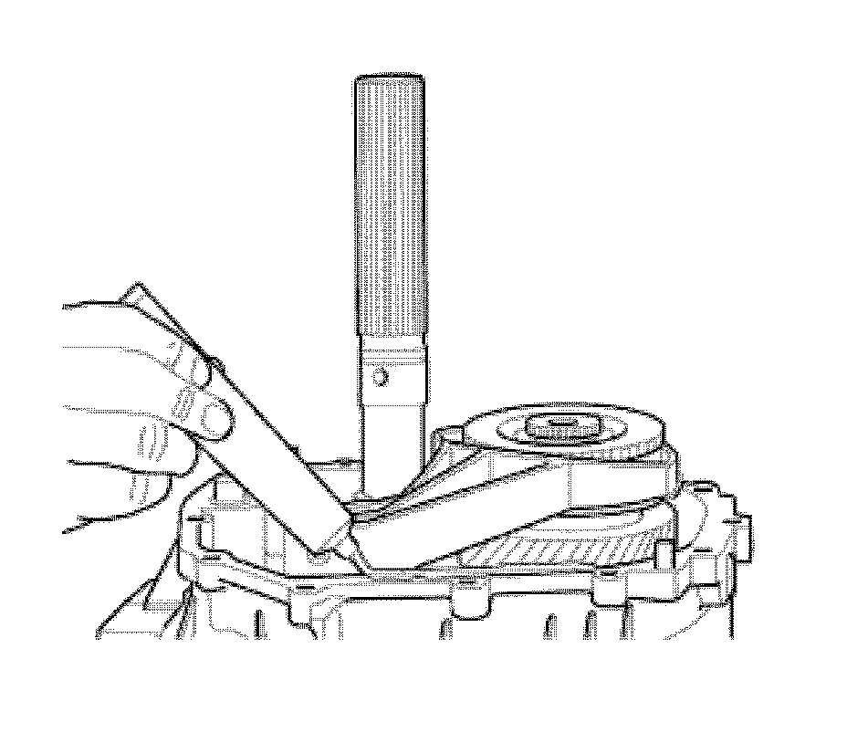
18. Clean the surface and apply sealant.
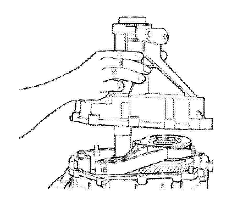
19. Install the extension, as shown.
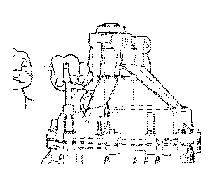
20. Using a 10 mm wrench, install the 12 screws that secure the casing.
21. Tighten the screws.
Tighten the screws to 24-37 N.m (18-28 lb ft).
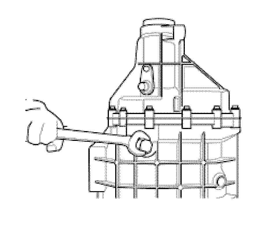
22. If removed, install the reverse lamp switch.
23. Tighten the reverse lamp switch.
Tighten the reverse lamp switch to 16-21 N.m (12-16 lb ft).
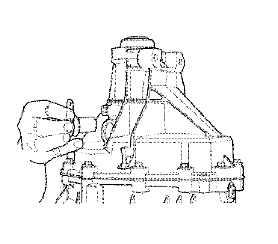
24. Install the vehicle speed sensor.
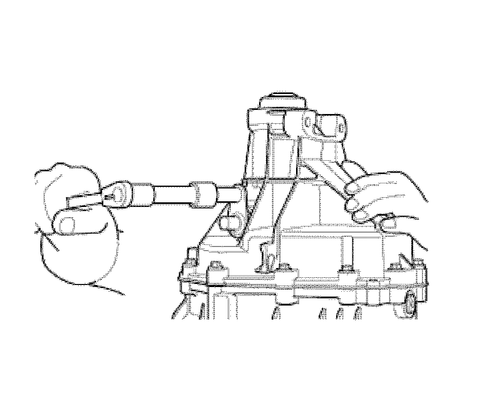
25. Using a 10 mm wrench, tighten the vehicle speed sensor bolt.
Tighten the vehicle speed sensor bolt to 16-21 N.m (12-16 lb ft).
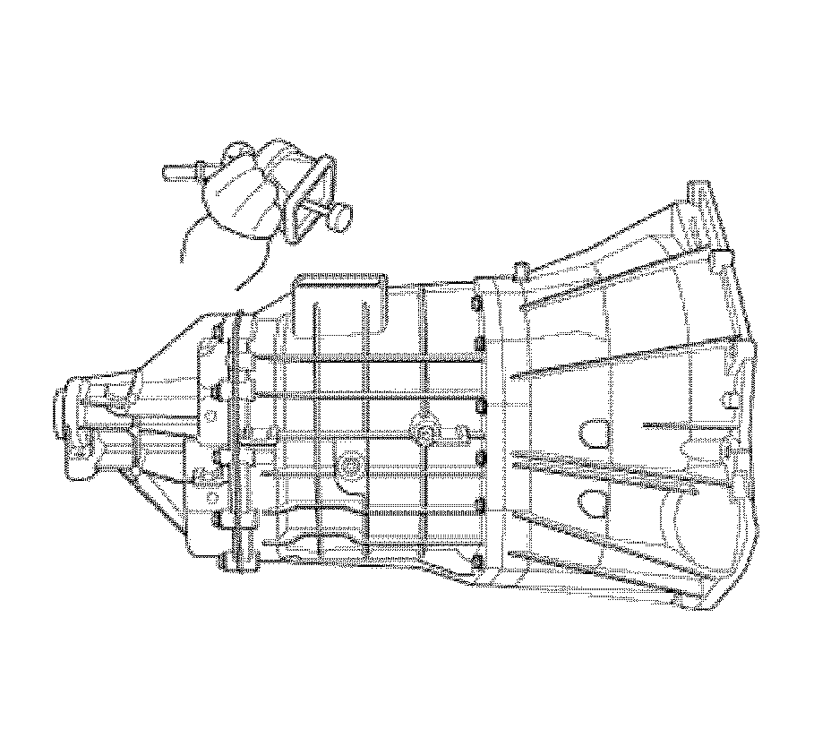
26. Install the shift tower.
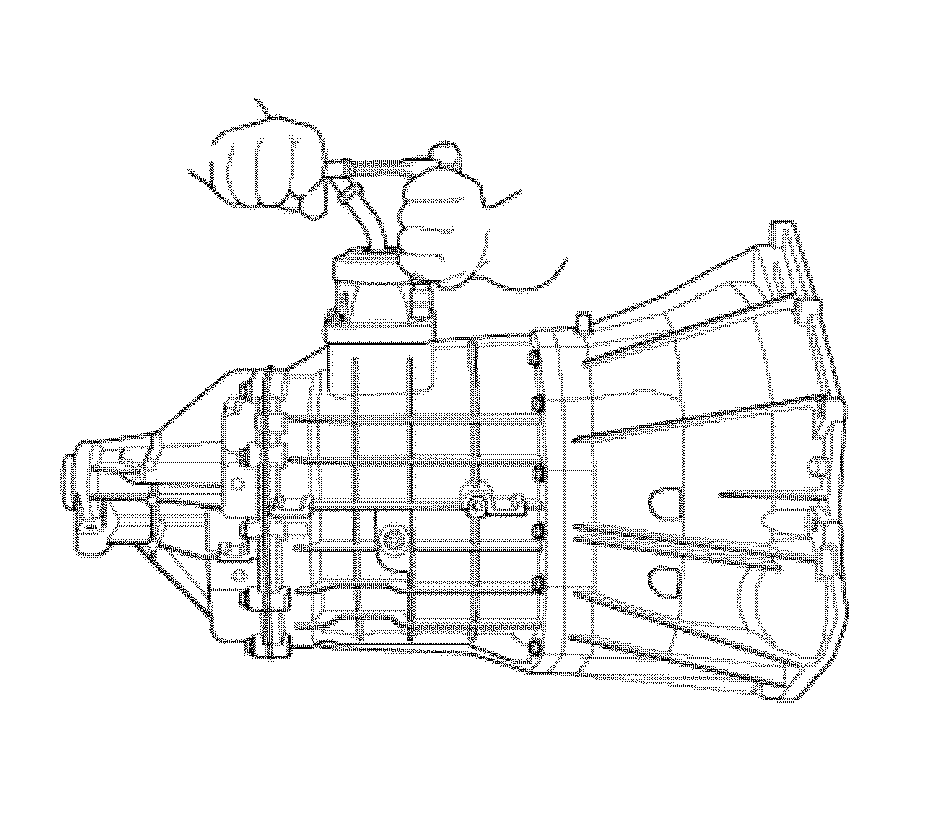
27. Using a 10 mm wrench, tighten the 4 shift tower screws.
Tighten the screws to 10-17 N.m (8-13 lb ft).