Main Shaft Assemble
Main Shaft Assemble
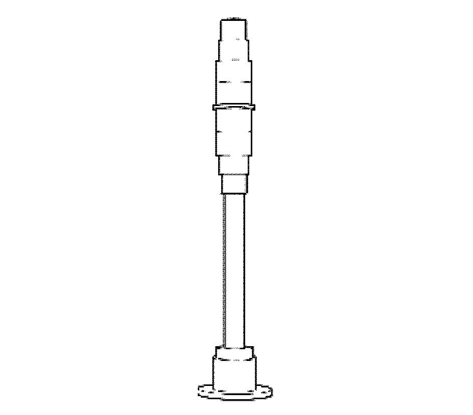
1. Place the main shaft on a workbench.
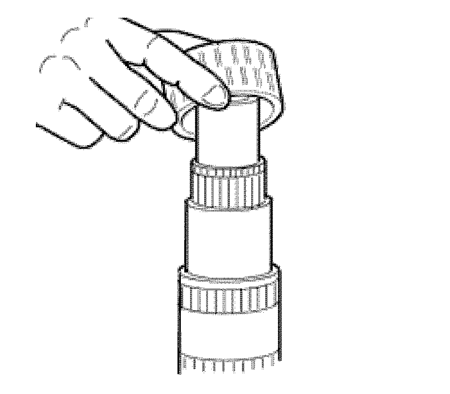
2. Install the 2nd speed gear roller cage.
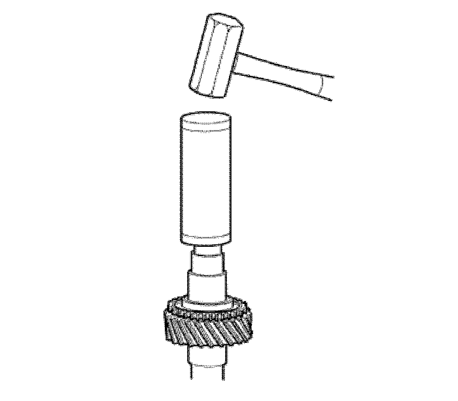
3. Using a press or driving tool, adjust 2nd speed gear and 3rd speed bushing.
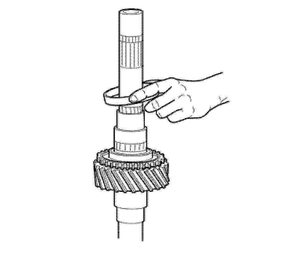
4. Install the 2nd speed gear inner ring.
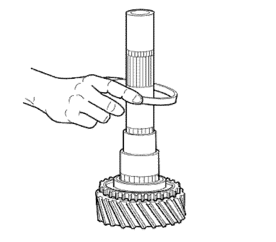
5. Install the 2nd speed gear intermediate ring.
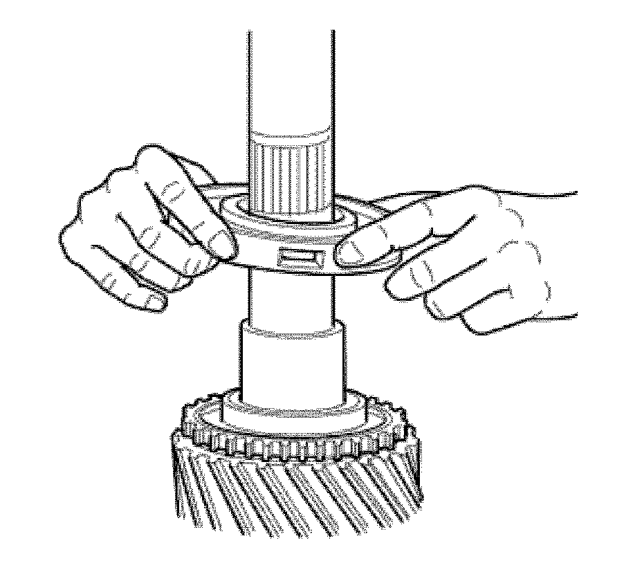
6. Install the 2nd speed gear synchronizer ring.
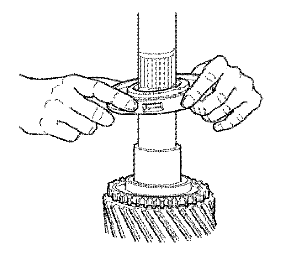
7. Install the 1st and 2nd speed synchronizer assembly.
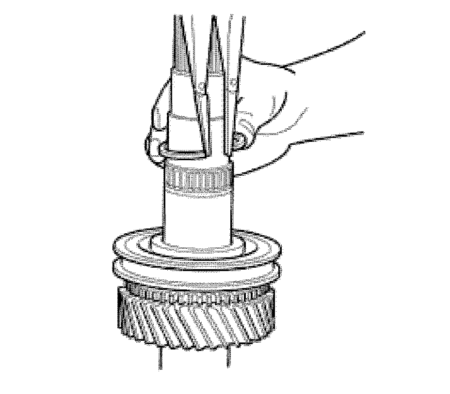
8. Using retainer pliers, install the retainer that secures the 1st and 2nd speed synchronizer drum.
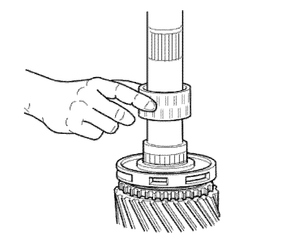
9. Install the 1st speed gear roller cage.
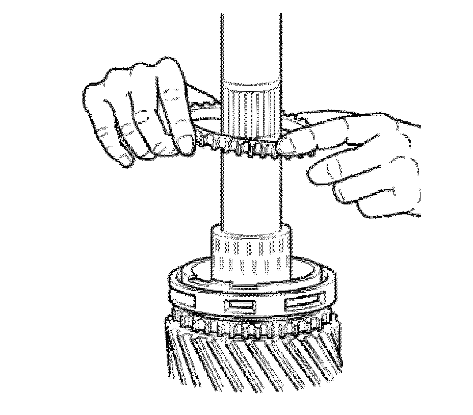
10. Install the 1st speed gear synchronizer ring.
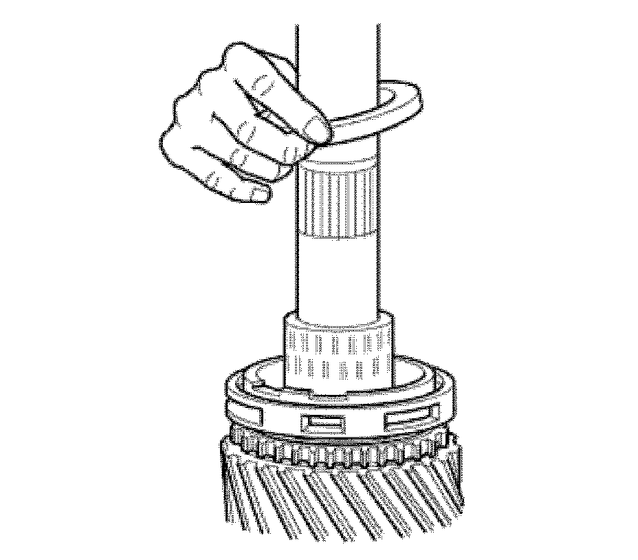
11. Install the 1st speed gear intermediate cone.
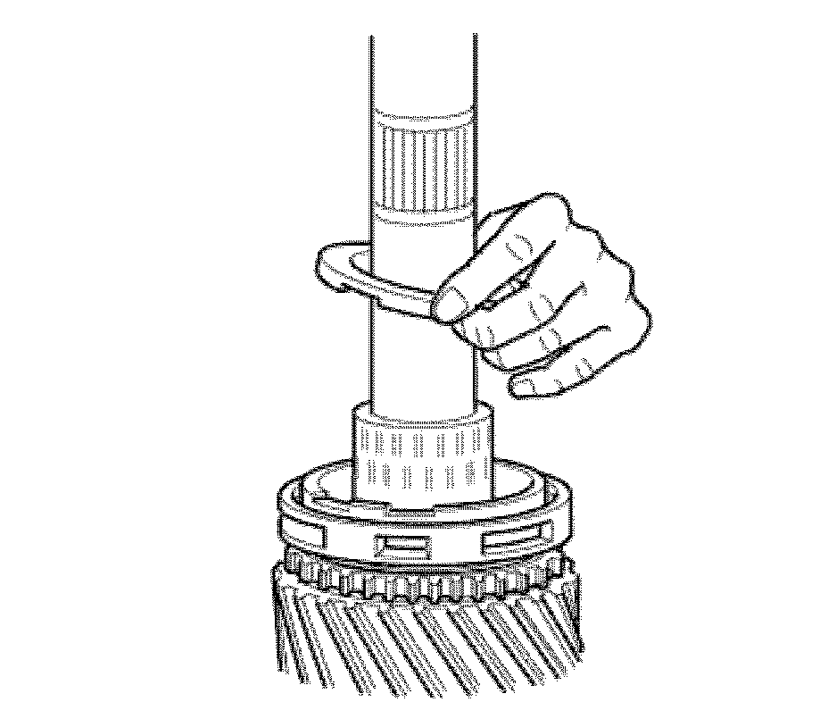
12. Install the 1st speed gear inner cone.
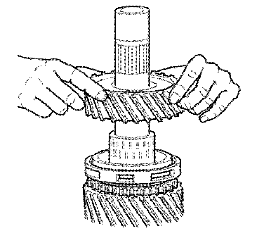
13. Install the 1st speed gear.

14. Install the reverse gear assembly coupling cone.
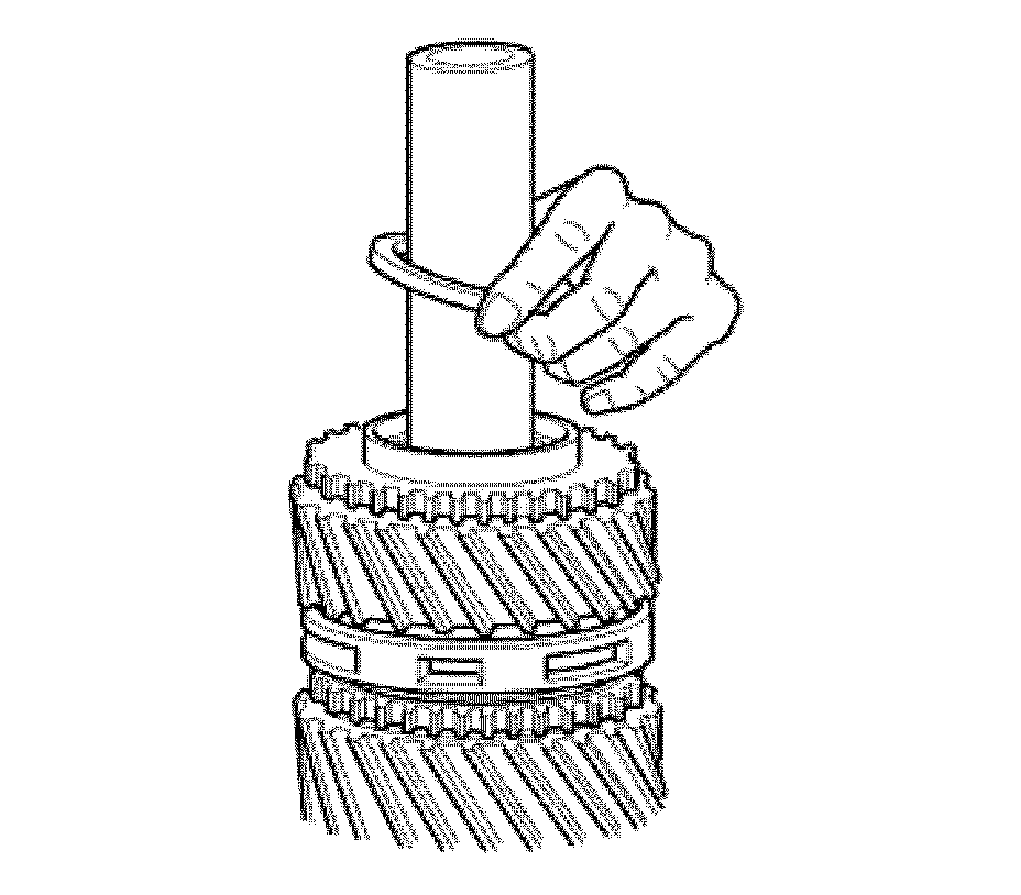
15. Install the reverse gear assembly synchronizer ring.
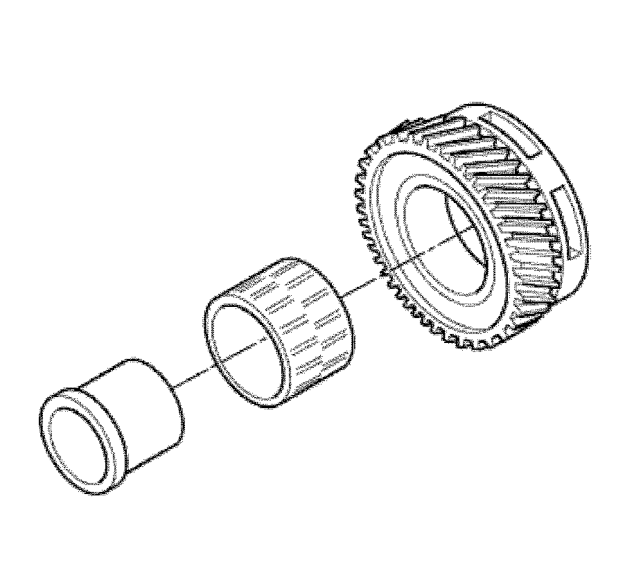
16. The reverse gear assembly arrangement shows the bushing, roller cage, and reverse gear assembly.
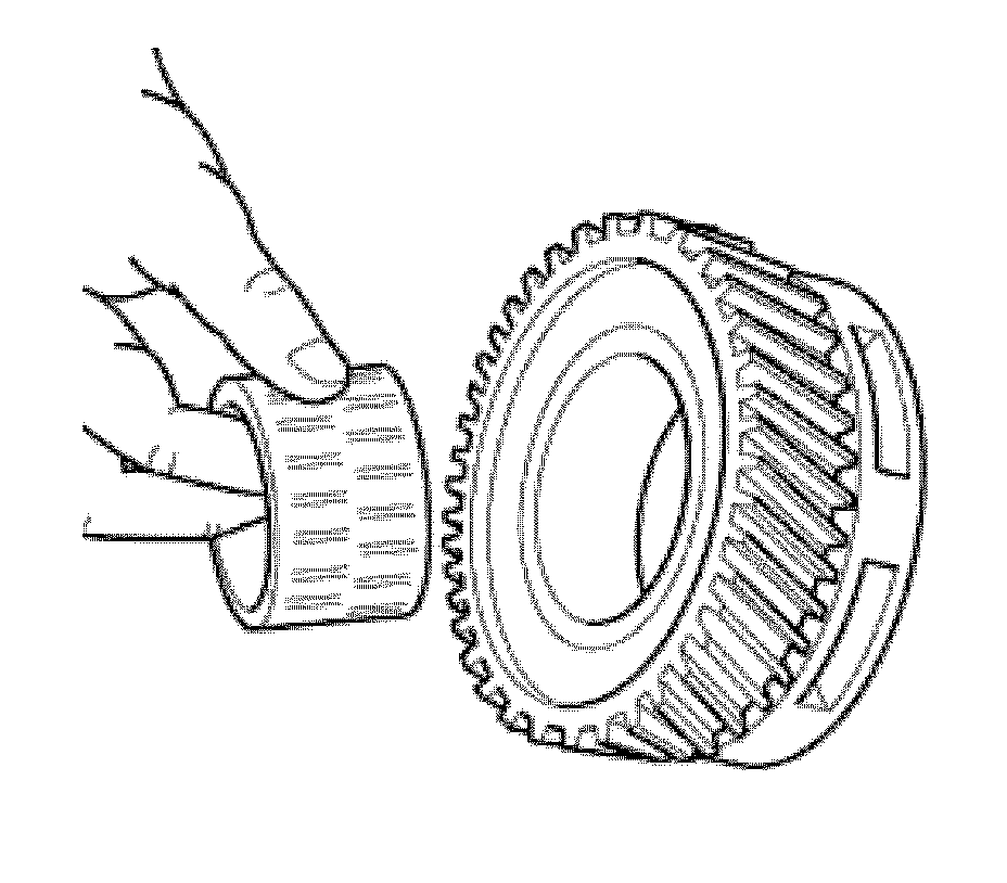
17. Install the reverse gear assembly cage.
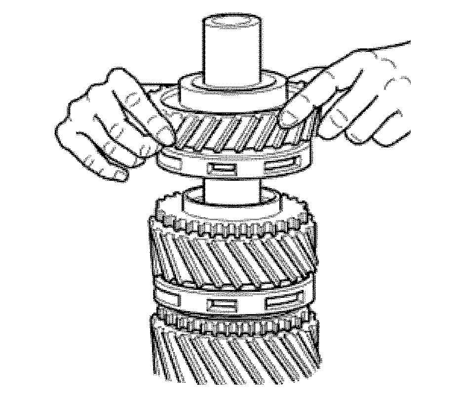
18. Install the reverse gear assembly bushing.
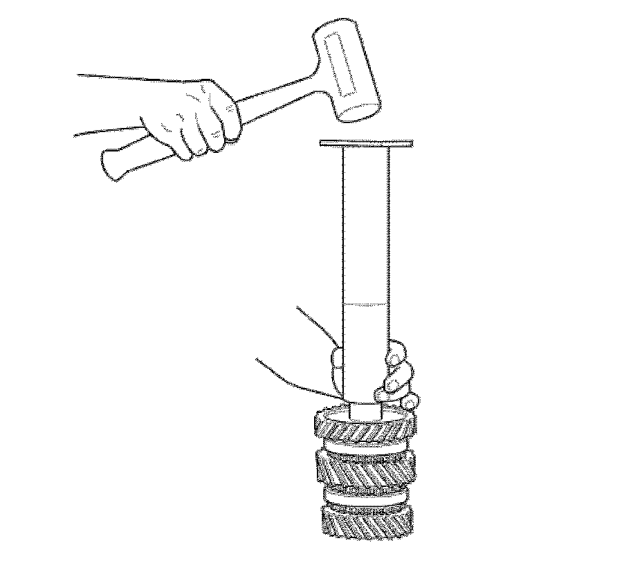
19. Using a press or a driving tool, install the reverse gear assembly bushing.
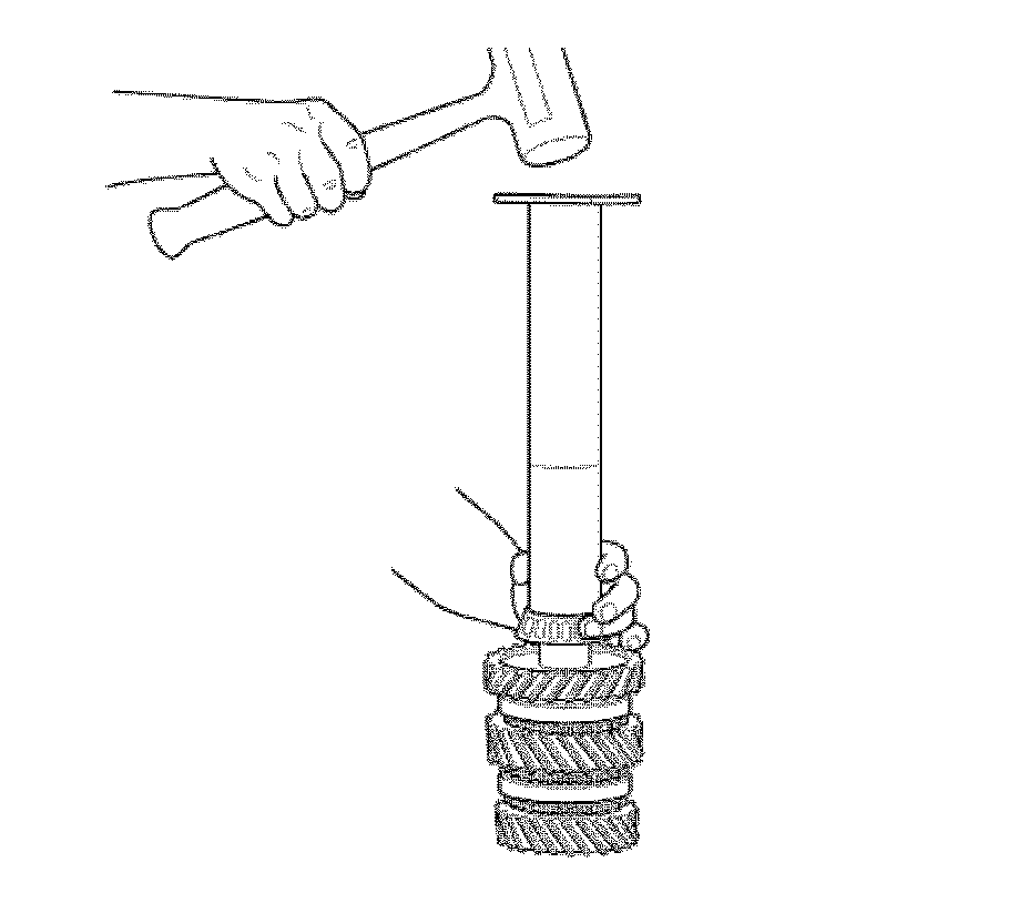
20. Using a press or driving tool, install the bearing cone.
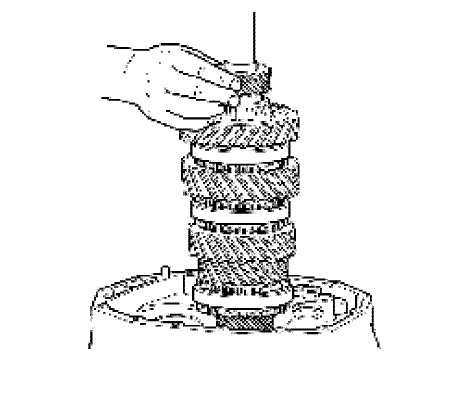
21. Install 5th speed gear.
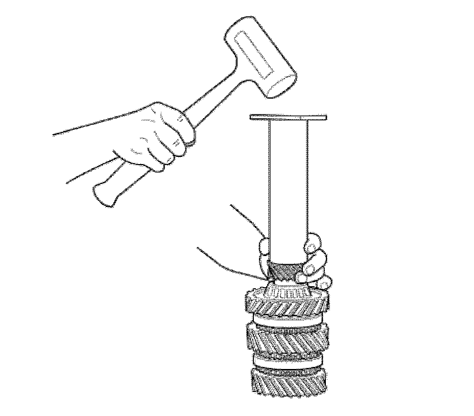
22. Using a press or driving tool, install 5th speed gear.
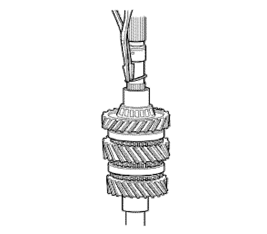
23. In the case of a 4 speed transmission, install the bushing instead of 5th speed gear.
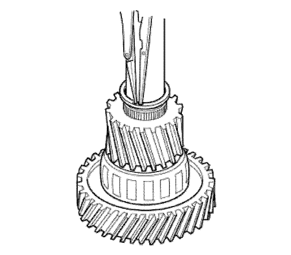
24. Using retainer pliers, install the 5th speed gear retainer.
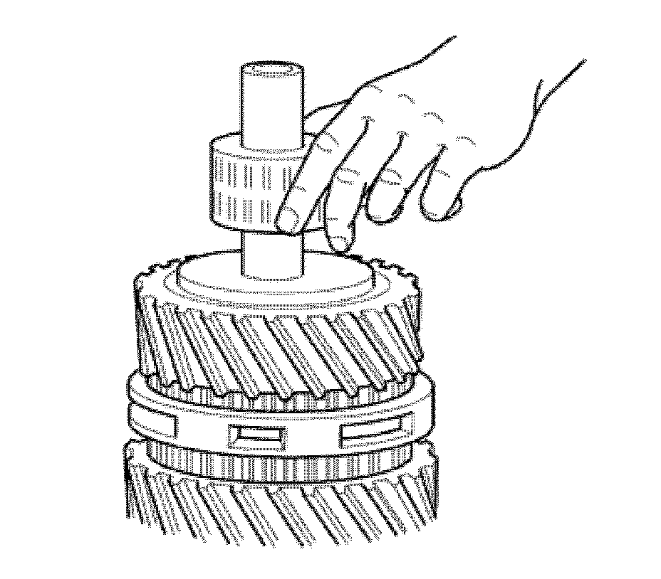
25. Turn the primary shaft assembly and install the 3rd speed gear roller cage.
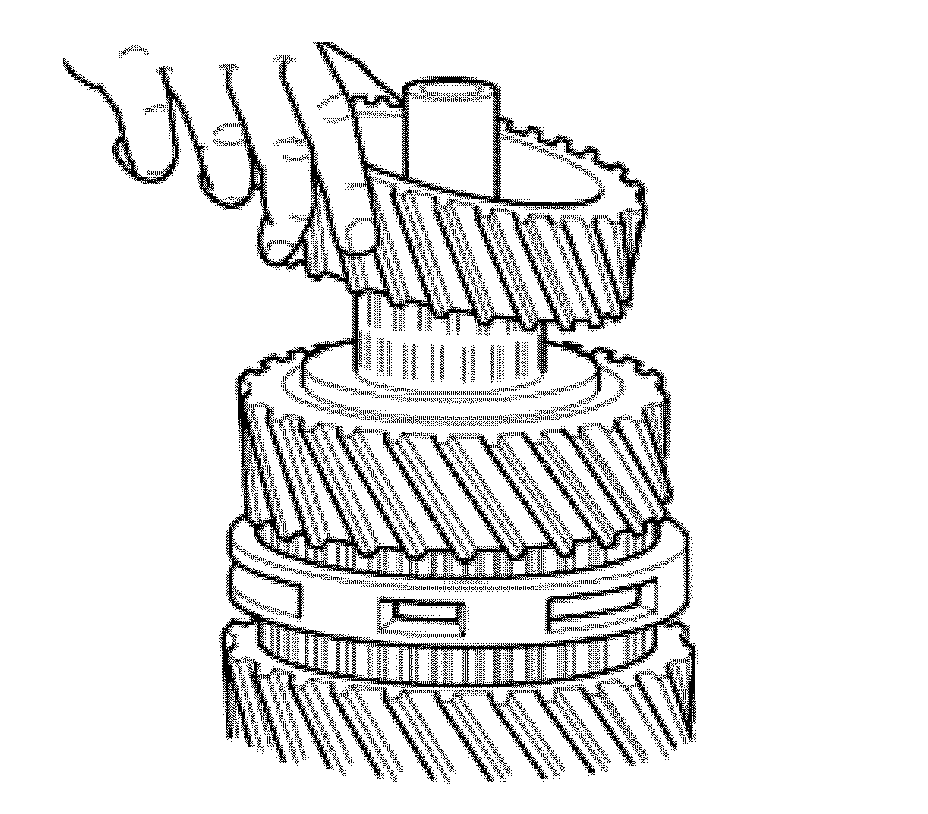
26. Install 3rd speed gear.
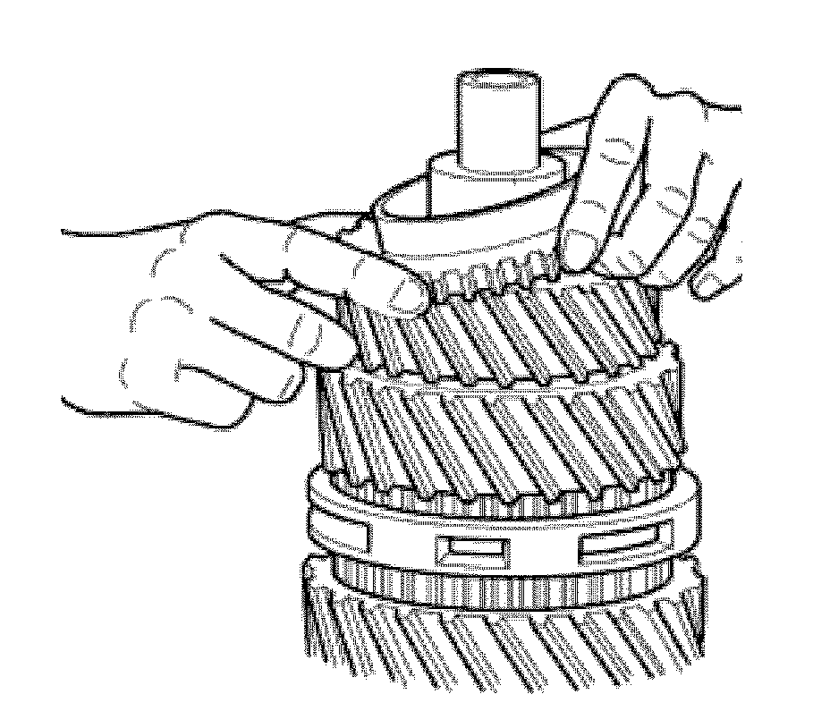
27. Install the 3rd speed gear cone.
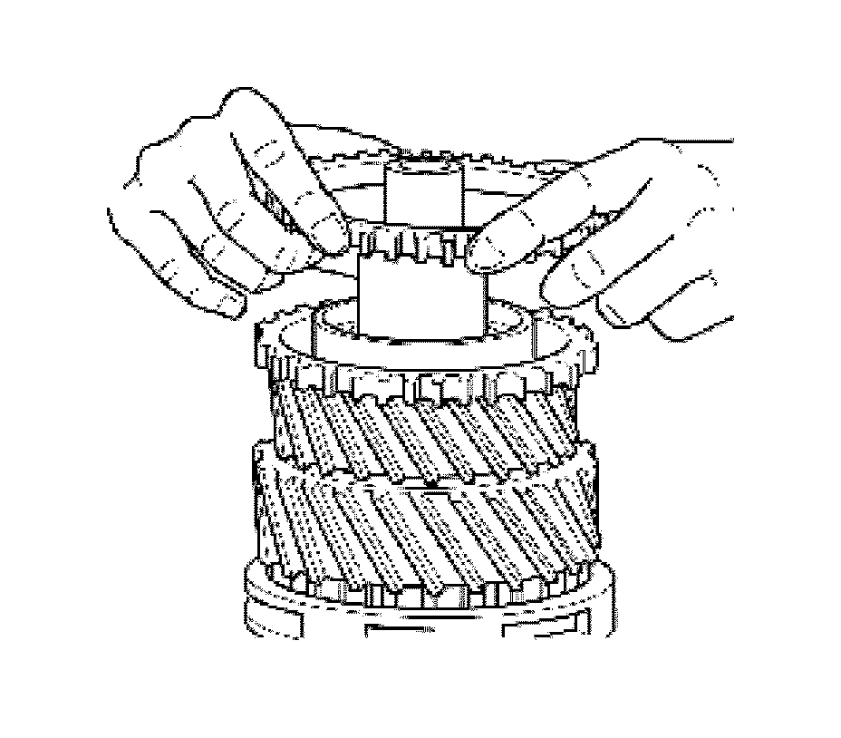
28. Install the 3rd speed gear synchronizer ring.
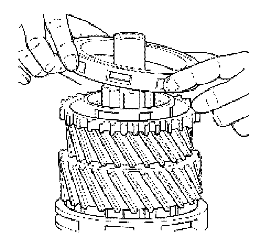
29. Install the 3rd and 4th speed synchronizer assembly.
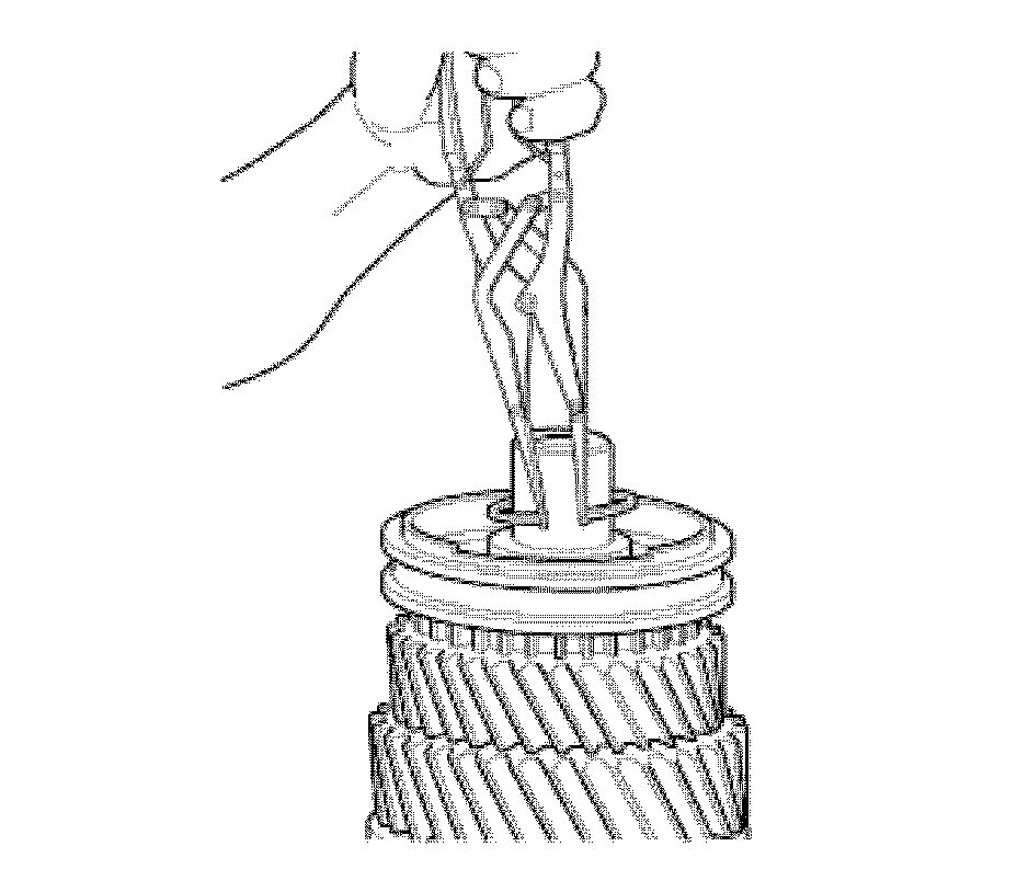
30. Using retainer pliers, install the 3rd and 4th synchronizer drum retainer.
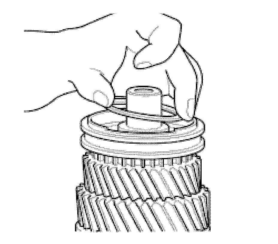
31. Install the drive wheel.
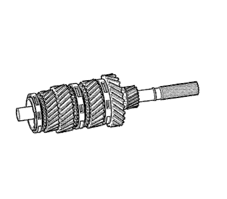
32. Installed main shaft assembly.