Shift Shaft and Fork Assemblies Disassemble
Shift Shaft and Fork Assemblies Disassemble
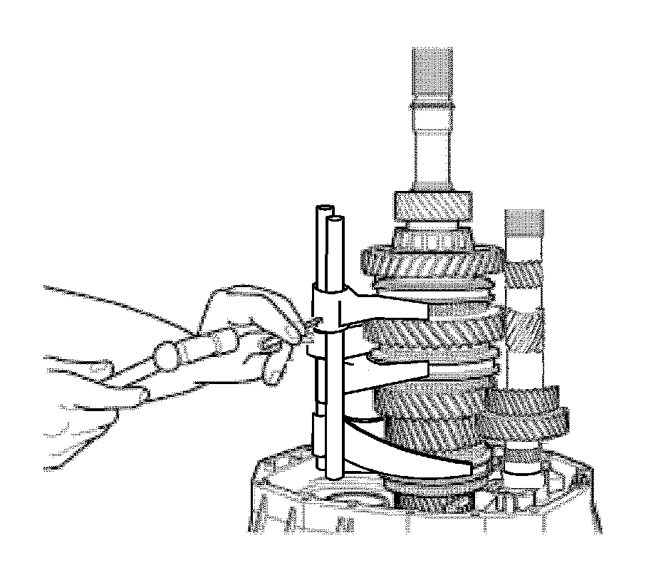
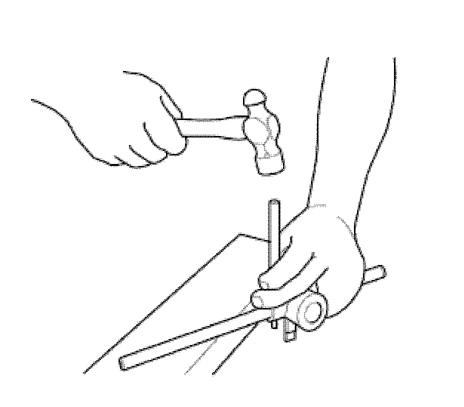
1. Using a hammer and a punch, remove the roll pin from the yoke and the reverse gearshift lever.
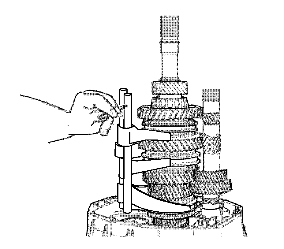
2. Using a punch, turn the reverse gearshift lever to free it from the roll pin and remove.
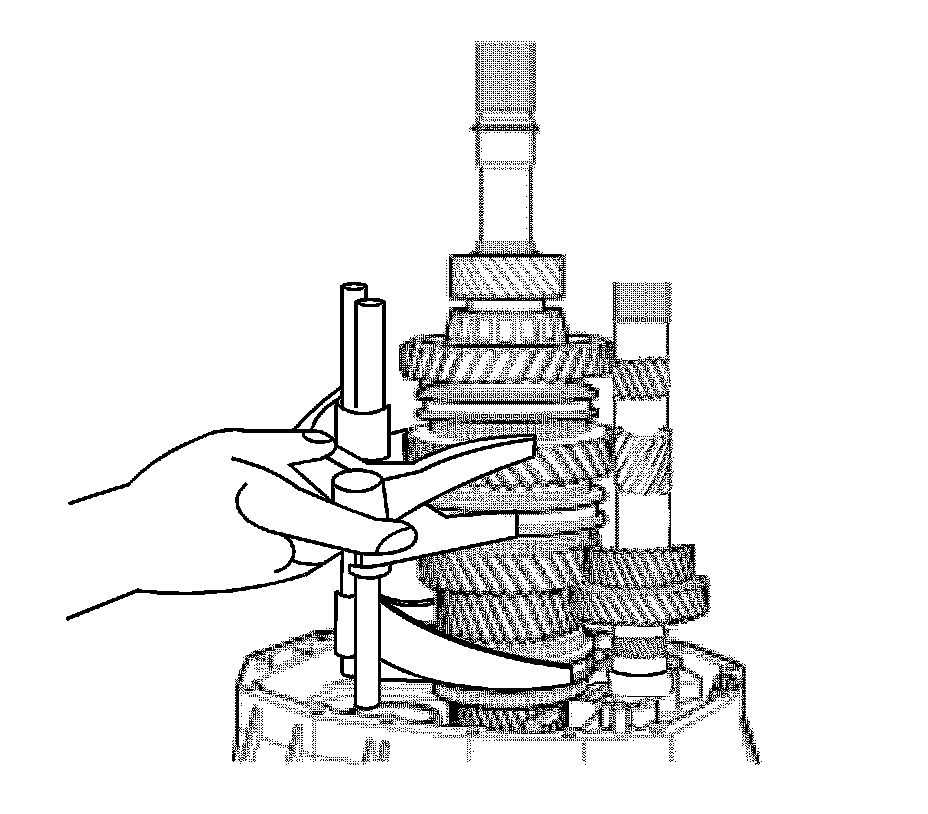
3. Remove the reverse fork.
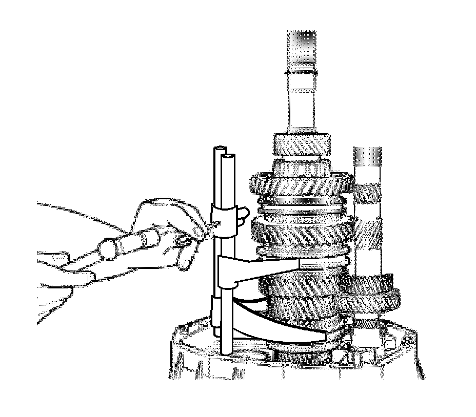
4. Remove the 1st and 2nd speed stop pin. Use care with the anchor bolt.
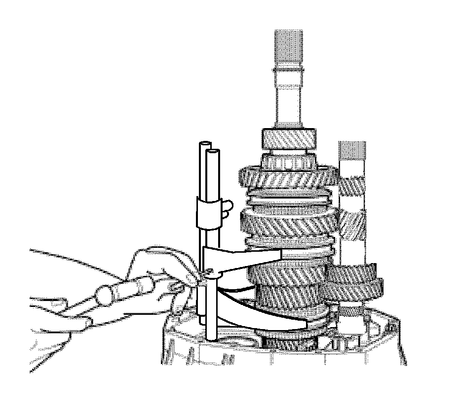
5. Using a punch and hammer, remove the retaining bolt from the fork and the 1st and 2nd lever.
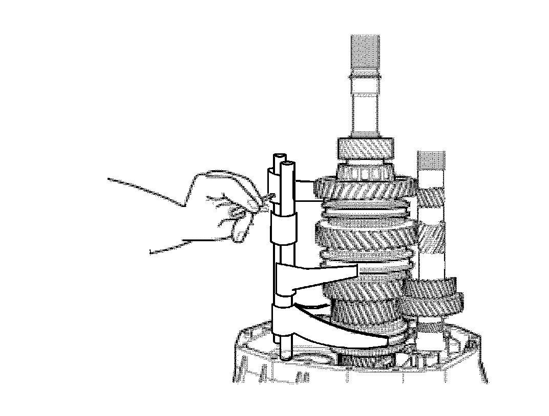
6. Using a punch, turn the 1st and 2nd lever to release it from the anchor bolt and remove it.
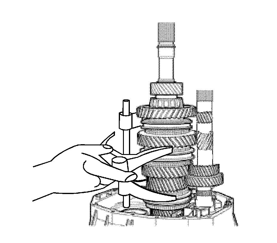
7. Remove the 1st and 2nd fork.
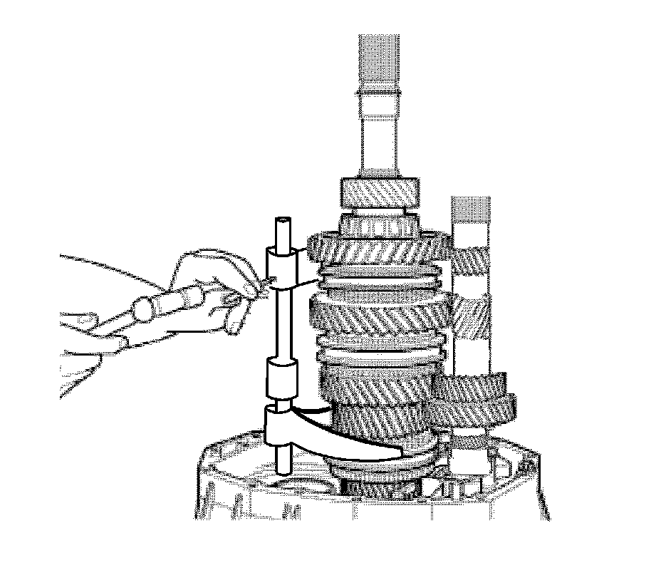
8. Using a punch and a hammer, remove the retaining bolt from the 3rd and 4th stop.
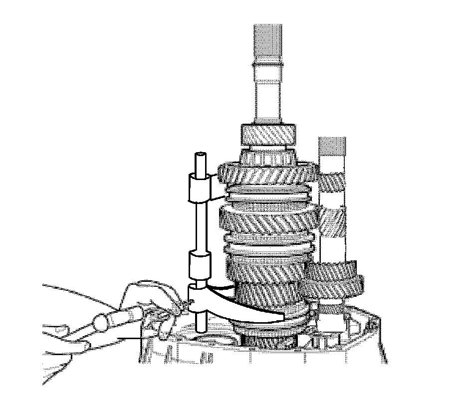
9. Using a punch and a hammer, remove the retaining bolt from the 3rd and 4th fork.
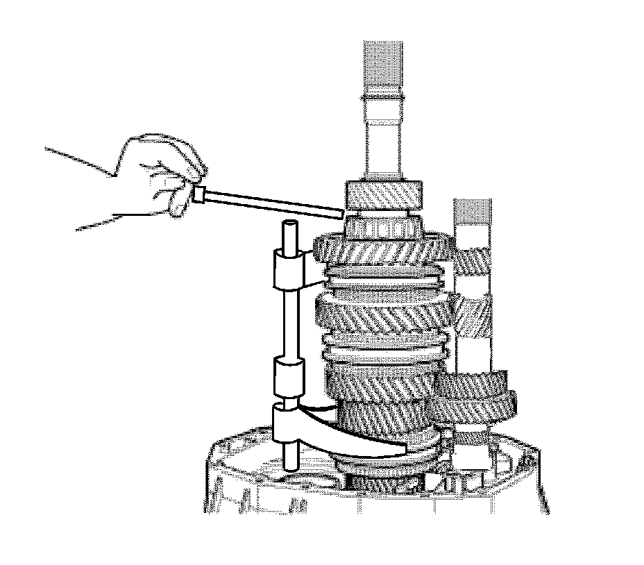
10. Using a punch, turn the 3rd and 4th lever to release it from the anchor bolt and remove it.
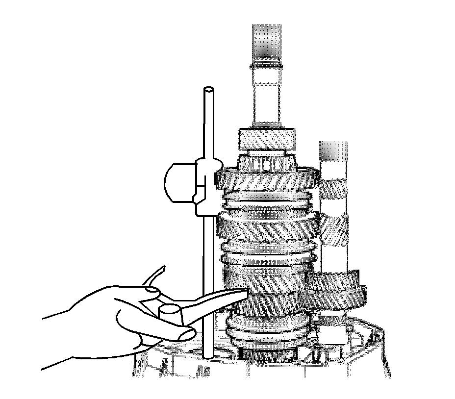
11. Remove the 3rd and 4th fork.
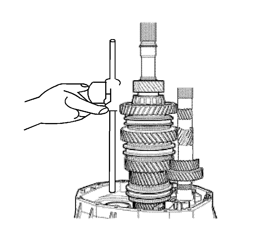
12. Remove the control lever.
13. Remove the speed selector stop pin, if necessary.