Wheel Drive Shaft Replacement
Wheel Drive Shaft Replacement (1500)
Caution: Do not attempt to move vehicle with drive axle(s) removed from wheel bearing. Wheel(s) could fall off, dropping vehicle to the ground and causing personal injury or damage to the vehicle.
Tools Required
J 45859 Axle Remover
Removal Procedure
1. Raise and support the vehicle. Refer to Lifting and Jacking the Vehicle .
2. Remove the tire and wheel. Refer to Tire and Wheel Removal and Installation (Service and Repair) .
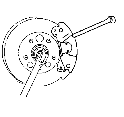
3. Insert a drift or large screwdriver through the brake caliper into one of the brake rotor vanes in order to prevent the wheel drive shaft from turning.
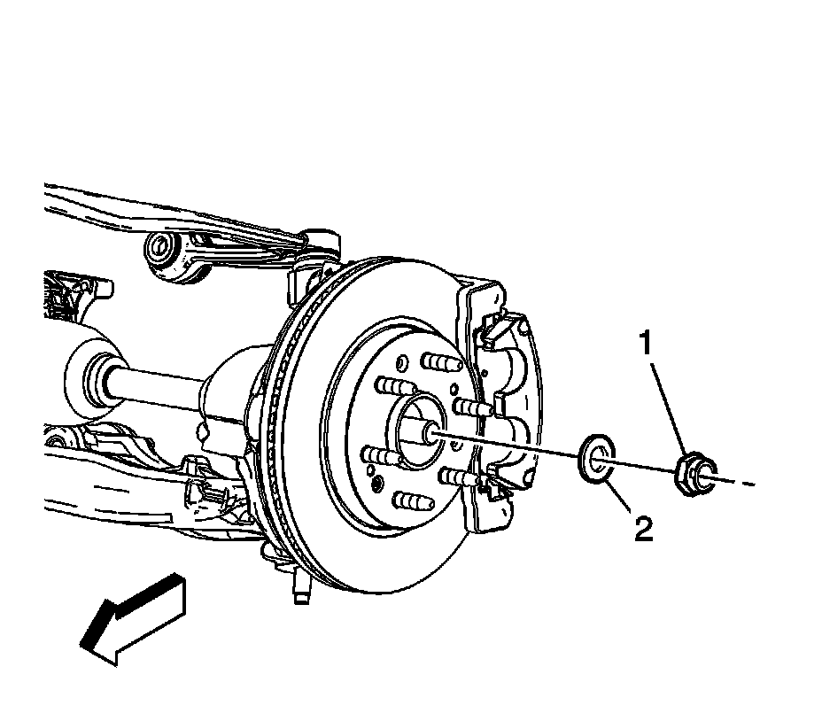
Important: DO NOT reuse the wheel drive shaft nut, use a NEW nut only.
4. Remove the nut (1) and washer (2) from the hub.
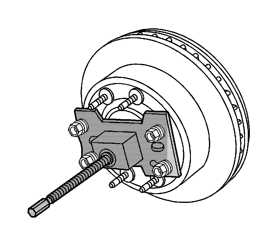
5. Using the J 45859 or equivalent, remove the wheel drive shaft from the hub.
6. Remove the special tool.
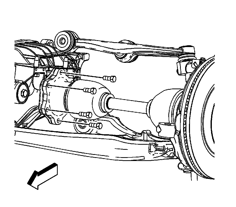
7. Remove the retaining bolts from the drive flange.
8. Remove the drift or large screwdriver from the brake rotor.
9. Remove the stabilizer shaft link from the lower control arm. Refer to Stabilizer Shaft Replacement (2500, 3500) (Service and Repair)Stabilizer Shaft Replacement (1500) (Service and Repair) .
10. Remove the shock module. Refer to Shock Absorber and Spring Assembly Replacement (Shock Absorber and Spring Assembly Replacement) .
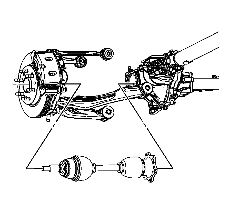
11. Remove the wheel drive shaft through the lower control arm opening.
12. Remove all dirt and debris from the splines on the wheel hub/bearing.
Installation Procedure
1. Install the wheel drive shaft in the steering knuckle.
Important: Install the NEW nut and washer, but DO NOT tighten at this time.
2. Install the NEW nut (1) and washer (2).
3. Install the retaining bolts and finger tighten.
4. Insert a drift or large screwdriver through the brake caliper into one of the brake rotor vanes in order to prevent the wheel drive shaft from turning.
Notice: Refer to Fastener Notice .
5. Tighten the wheel driver shaft retaining bolts.
Tighten the retaining bolts to 79 N.m (58 lb ft).
6. Tighten the wheel drive shaft retaining nut.
Tighten the retaining nut to 240 N.m (177 lb ft).
7. Remove the drift or large screwdriver from the brake rotor.
8. Install the shock module. Refer to Shock Absorber and Spring Assembly Replacement (Shock Absorber and Spring Assembly Replacement) .
9. Install the stabilizer shaft link from the lower control arm. Refer to Stabilizer Shaft Replacement (2500, 3500) (Service and Repair)Stabilizer Shaft Replacement (1500) (Service and Repair) .
10. Install the tire and wheel. Refer to Tire and Wheel Removal and Installation (Service and Repair) .
11. Lower the vehicle.