Transmission Fluid Pump Cover Disassemble
Transmission Fluid Pump Cover Disassemble
Tools Required
* J 24459-5 Spring Compressor Adapter
* J 43770 Main Lube, Converter Relief Valve Spring Compressor
* J 43773 Valve Spring Compressor
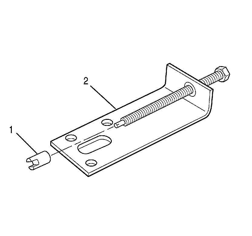
1. Install J 24459-5 (1) onto J 43770 (2).
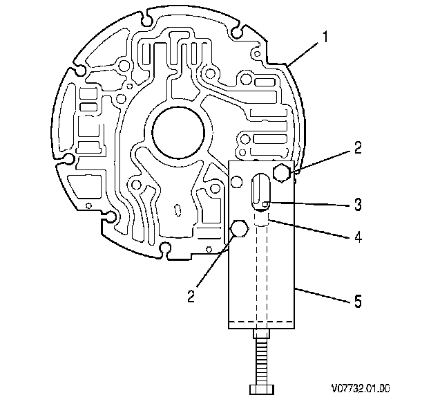
2. Position the oil pump cover assembly (1) on the work table so that the rear of the oil pump cover assembly is facing down.
3. Align J 43770 (5) and J 24459-5 (4) with the oil pump cover so that:
* The threaded rod of J 43770 is facing down.
* Two bolt holes of J 43770 align with the bolt holes of the oil pump cover.
4. Install J 43770 (5) onto the oil pump cover assembly.
5. Install 2 oil pump cover retaining bolts (2).
6. Align the slot of J 24459-5 (4) with the retainer pin (3).
7. Using J 24459-5 (4) and J 43770 (5), compress the main regulator valve spring until the retainer pin (3) is loose.
8. Turn the oil pump cover so that the pin (3) is accessible.
9. Using a pick, push the pin through the oil pump cover (1).
10. Relieve the main regulator valve spring tension.
11. Remove tools J 43770 and J 24459-5 .
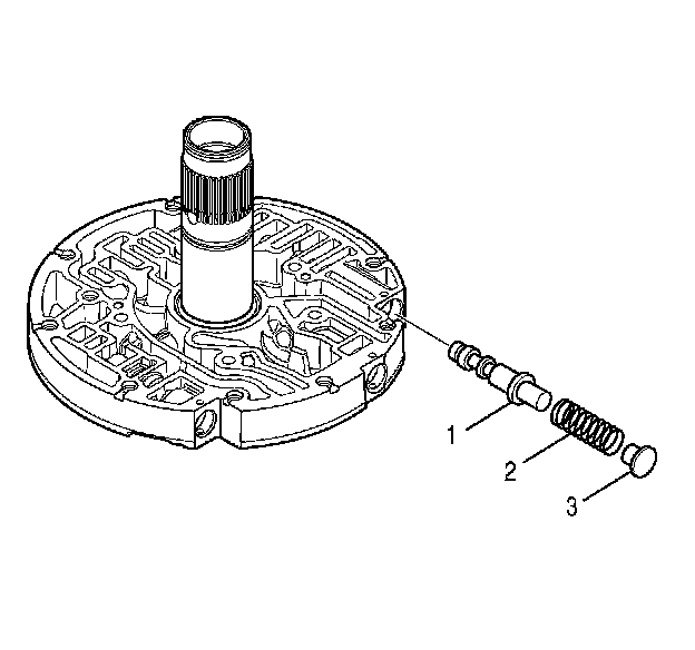
12. Remove the stop (3), the spring (2), and the main regulator valve (1).
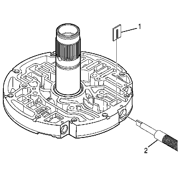
13. Using J 43773 (2), compress the 1-2-3-4 clutch backfill valve spring until the retaining clip (1) is loose.
14. Remove the clip.
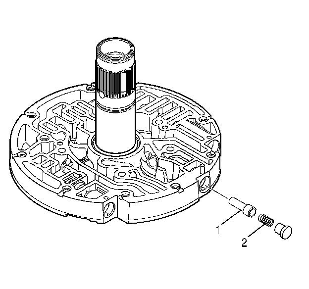
15. Remove the spring (2) and the 1-2-3-4 clutch backfill valve (1).
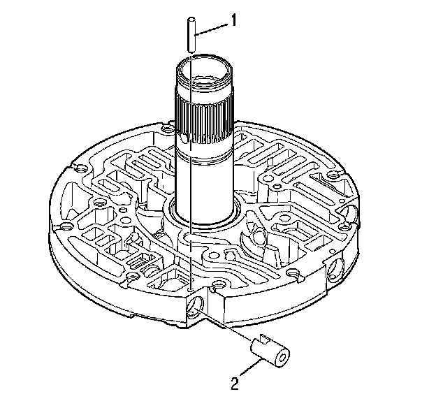
16. Align the slot of J 24459-5 (2) with the retainer pin (1).
17. Using J 24459-5 (2), compress the lube regulator valve spring until the retainer pin (1) is loose.
18. Remove the pin.
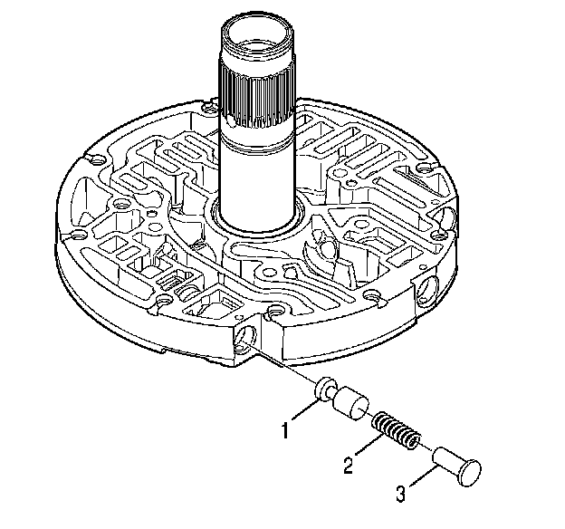
19. Remove the stop (3), the spring (2) and the lube regulator valve (1).
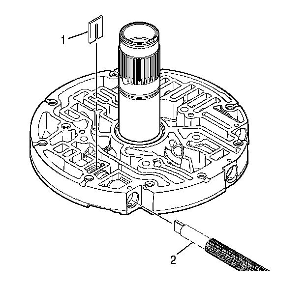
20. Using J 43773 (2), compress the converter relief valve spring until the retaining clip (1) is loose.
21. Remove the clip.
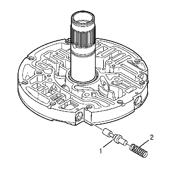
22. Remove the spring (2) and the converter relief valve (1).
23. Install J 24459-5 (1) onto J 43770 (2).
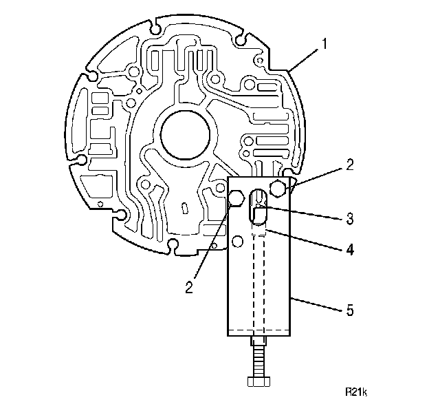
24. Align J 43770 (5) and J 24459-5 (4) with the oil pump cover so that the following conditions are met:
* The threaded rod of J 43770 is facing down.
* Two J 43770 bolt holes align with 2 bolt holes in the oil pump cover.
25. Install J 43770 (5) onto the oil pump cover assembly (1).
26. Install 2 oil pump cover retaining bolts (2).
27. Align the slot in J 24459-5 (4) with the retainer pin (3).
28. Using J 24459-5 (4) and J 43770 (5), compress the torque converter clutch (TCC) valve spring until the retainer pin (3) is loose.
29. Using a pick, push the pin through the oil pump cover (1).
30. Turn the oil pump cover so that the retaining pin is accessible.
31. Relieve the TCC valve spring tension.
32. Remove tools J 43770 (5) and J 24459-5 (4) .
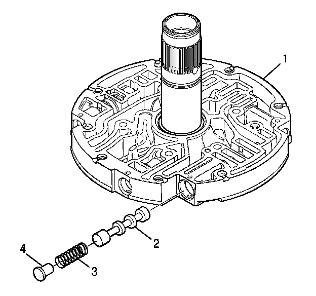
33. Remove the stop (4), the spring (3), and the TCC valve (2).