Steering Shaft Upper Bearing Replacement
Steering Shaft Upper Bearing Replacement
Tools Required
* J 21854-01 Pivot Pin Remover
* J 23653-SIR Steering Column Lock Plate Compressor
* J 42137 Cam Orientation Plate Adapter
* J 42640 Steering Column Anti-Rotation Pin
Removal Procedure
Caution: Refer to SIR Caution .
1. Remove the steering column. Refer to Steering Column Replacement (Non Hybrid) (Steering Column Replacement (Non Hybrid)) .
2. Remove the inflatable restraint steering wheel module coil. Refer to Inflatable Restraint Steering Wheel Module Coil Replacement .
3. Remove the turn signal multifunction switch. Refer to Turn Signal Multifunction Switch Replacement (Turn Signal Multifunction Switch Replacement) .
4. Remove the ignition lock cylinder case. Refer to Ignition Lock Cylinder Case Replacement .
5. Remove the tilt spring. Refer to Steering Column Tilt Spring Replacement (Steering Column Tilt Spring Replacement) .
6. Remove the automatic transmission control. Refer to Transmission Control Replacement (Transmission Control Replacement) .
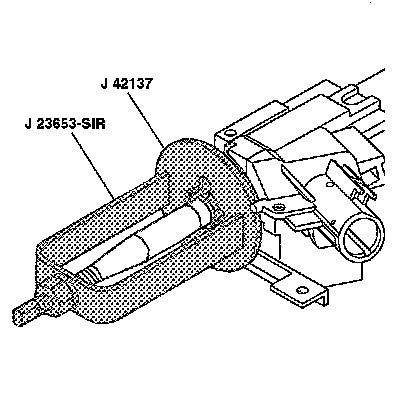
7. Using compressor J 23653-SIR and adapter J 42137 , remove and discard the steering shaft lock plate retaining ring .
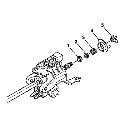
8. Remove the following parts from the steering column shaft assembly:
1. The turn signal switch cancel cam position plate (5)
2. The turn signal switch cancel cam (4)
3. The steering shaft upper bearing spring (3)
4. The steering shaft upper bearing inner race seat (2)
5. The steering shaft upper bearing inner race (1)
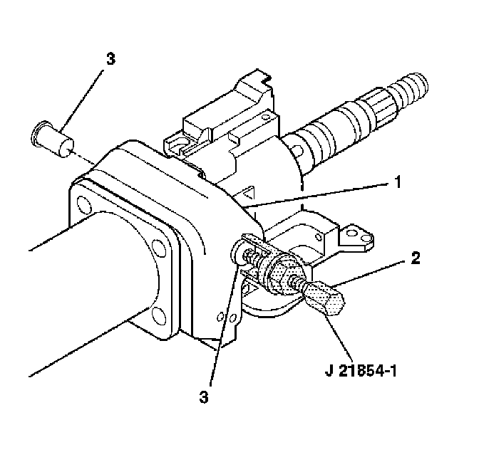
9. Remove the 2 pivot pins (3) from the steering column tilt head assembly (1) by using remover J 21854-01 (2) .
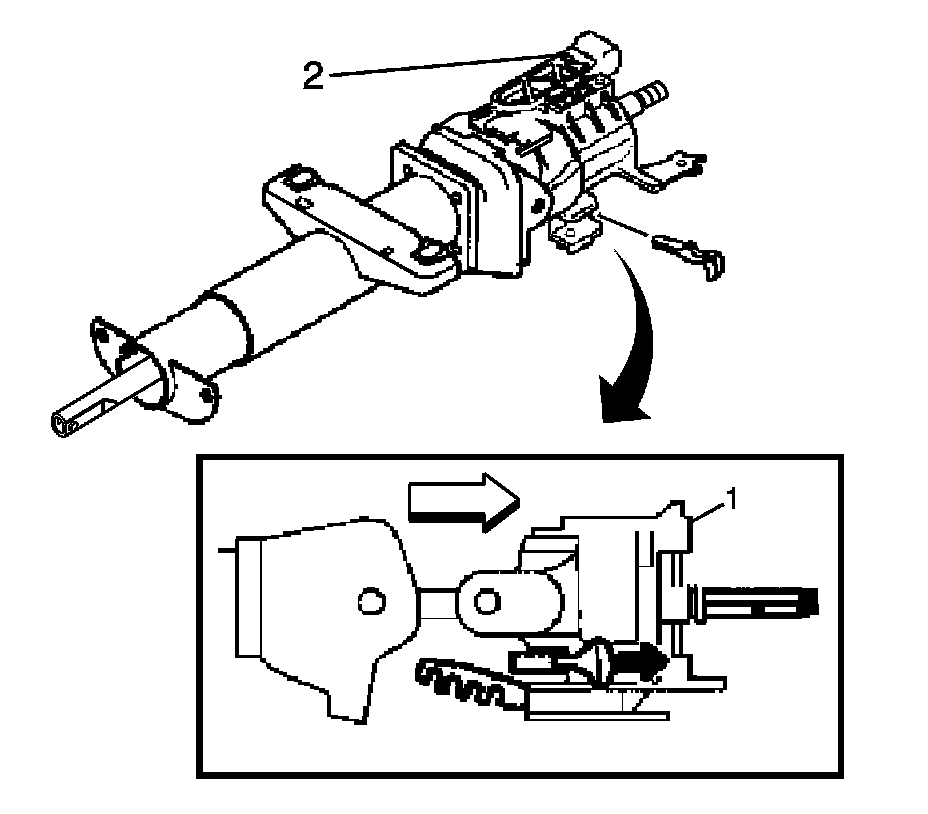
10. Install the tilt lever into the steering column tilt head assembly (1).
11. Pull back on the tilt lever and at the same time, pull the steering column tilt head assembly (1) down and away from the steering column.
12. Remove the steering column tilt head assembly.
13. Remove anti-rotation pin J 42640 .
14. Remove the tilt lever.
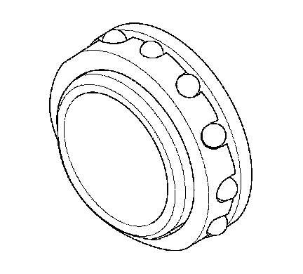
15. Remove the steering shaft upper bearing from the steering column tilt head assembly.
Installation Procedure
1. Install the steering shaft upper bearing to the steering column tilt head assembly.
2. Install the steering column shaft assembly.
3. Maneuver and push the steering column tilt head assembly (1) towards the steering column in order to lock the steering wheel lock shoes in place.
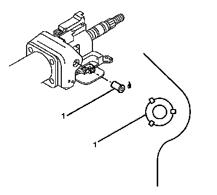
4. Lubricate the pivot pins (1) with GM P/N 12346293 (Canadian P/N 992723).
5. Firmly seat each pivot pin (1) into the steering column tilt head assembly.
6. Stake the steering column in 3 locations around each pivot pin.
7. Install anti-rotation pin J 42640 .
8. Install the following parts onto the steering column shaft assembly:
1. Lubricate the steering shaft upper bearing inner race (1) with GM P/N 12345718 (Canadian P/N 10953516).
2. The steering shaft upper bearing inner race (1)
3. The steering shaft upper bearing inner race seat (2)
4. The steering shaft upper bearing spring (3)
5. Lubricate the turn signal switch cancel cam (4) with GM P/N 12377900 (Canadian P/N 10953529).
6. The turn signal switch cancel cam (4)
7. The turn signal switch cancel cam position plate (5)
9. Install the new steering shaft lock plate retaining ring onto the steering shaft using compressor J 23653-SIR and adapter J 42137 .
10. Install the automatic transmission control assembly. Refer to Transmission Control Replacement (Transmission Control Replacement) .
11. Install the tilt spring. Refer to Steering Column Tilt Spring Replacement (Steering Column Tilt Spring Replacement) .
12. Install the ignition lock cylinder case. Refer to Ignition Lock Cylinder Case Replacement .
13. Install the turn signal multifunction switch. Refer to Turn Signal Multifunction Switch Replacement (Turn Signal Multifunction Switch Replacement) .
14. Install the inflatable restraint steering wheel module coil. Refer to Inflatable Restraint Steering Wheel Module Coil Replacement .
15. Install the steering column. Refer to Steering Column Replacement (Non Hybrid) (Steering Column Replacement (Non Hybrid)) .