Rear Axle Hub, Bearing, Cup, and/or Seal Replacement
Special Tools
- J 2222-C Wheel Bearing Nut Wrench
- J 8092 Universal Driver Handle - 3/4 x 10 inch
- J 24426 Outer Wheel Bearing Race Installer
- J 24427 Inner Wheel Bearing Race Installer
- J 44419 Hub Bearing Installer
- J 44420 Differential Bearing Installer
Removal Procedure
Note:
- The wheel speed sensor ring is NOT serviced separately. The hub and wheel speed senor ring are serviced as an assembly.
- The rear axle hub seal must be replaced anytime the rear axle hub assembly is removed from the axle housing.
- The wheel studs are serviced separately from the rear axle hub.
1. Raise and support the vehicle.
2. Remove the tire and wheel assembly.
Note: In the following service procedure, it is not necessary to remove the brake caliper from the bracket.
3. Remove the brake caliper bracket. Refer to Rear Brake Caliper Bracket Replacement Removal and Replacement.
4. Remove the rear axle shaft. Refer to Rear Axle Shaft and/or Gasket Replacement Service and Repair.
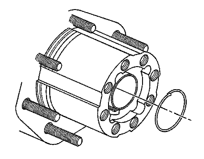
5. Remove the rear axle nut retaining ring.
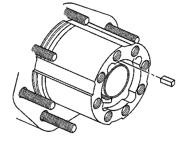
6. Remove the rear wheel bearing adjuster key.
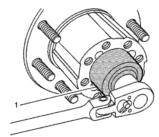
7. Using the J 2222-C wrench , remove the rear wheel bearing adjuster nut.
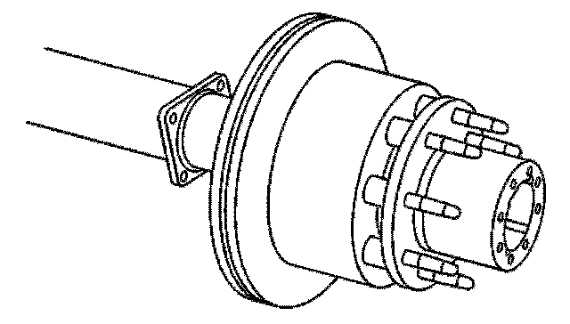
Note: If the oil seal remains on the axle hub, remove the seal using a suitable seal removal tool.
8. Remove the rear axle hub from the axle housing.
9. Remove the rear brake rotor, if necessary. Refer to Rear Brake Rotor Replacement Service and Repair.
10. Using a suitable seal removal tool, remove the oil seal from the wheel hub.
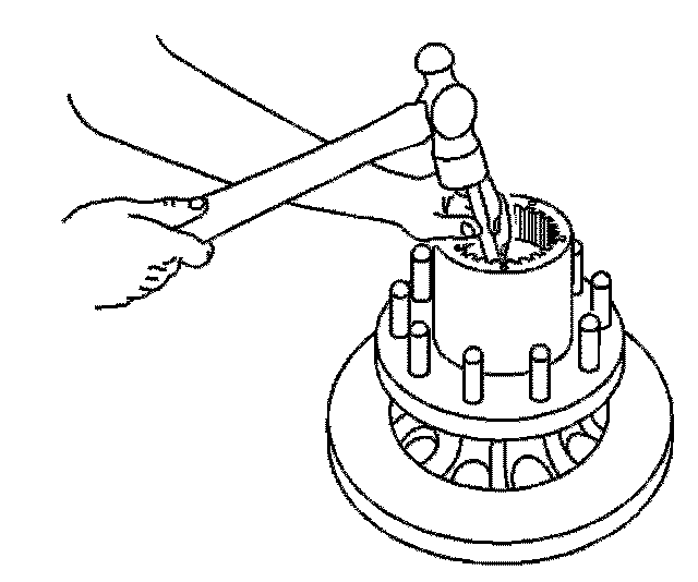
11. Remove the inner hub bearing.
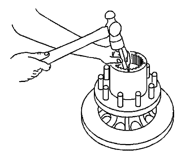
12. Using a brass drift and a hammer, remove the inner hub bearing cup.
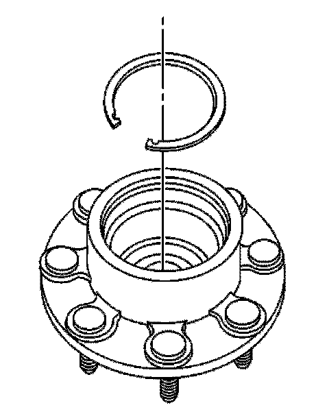
13. Remove the retaining ring from the wheel hub.
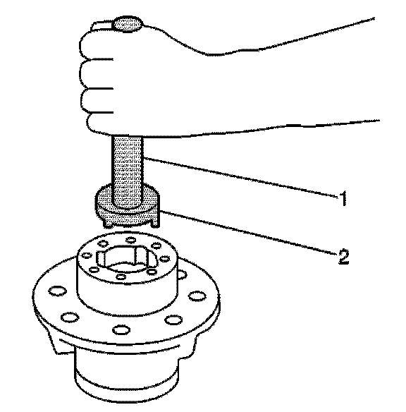
14. Using the J 24426 installer (2) and the J 8092 handle (1), remove the outer hub bearing and bearing cup.
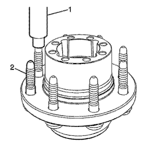
15. For those vehicles equipped with RPO code JH6, use the J 45270 (1) to remove the wheel studs (2).
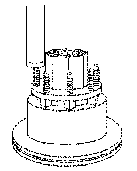
16. For those vehicles equipped with RPO code JH7, use a hydraulic press to remove the wheel studs.
17. Remove the rear brake disc from the rear axle hub.
Installation Procedure
1. For vehicles equipped RPO code JH7, position the brake rotor on the rear axle hub.
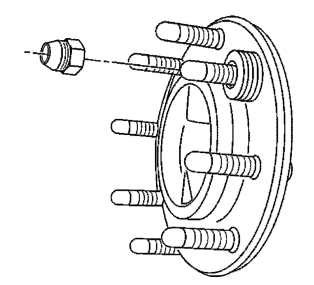
2. Position the wheel stud in the rear axle hub.
3. Using washers and a wheel nut, tighten the wheel nut until the wheel stud is fully seated in the rear axle hub.
4. Remove the lug nut and the washers.
5. Lubricate the following with a light coat of high melting point EP bearing lubricant:
- The outer wheel bearing
- The inner wheel bearing
- The outer wheel bearing cup
- The inner wheel bearing cup
- The axle hub spindle
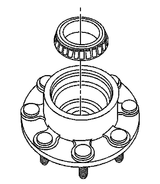
6. Install the outer bearing into the rear axle hub.
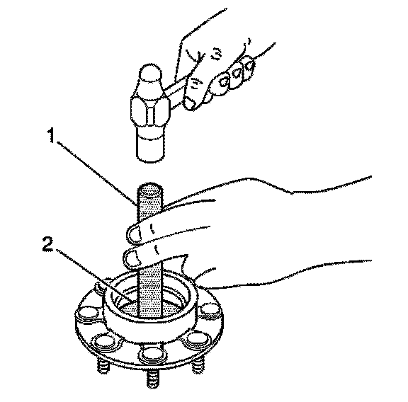
Note: Drive the outer bearing cup into the wheel hub until it is just past the retaining ring groove. Do not bottom out the bearing assembly in the bore.
7. Using the J 44419 installer (2) and the J 8092 handle (1), install the outer bearing cup into the rear axle hub.
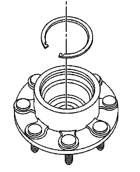
Note: Ensure that the retaining ring is fully and evenly seated in the groove.
8. Install the retaining ring into the groove.
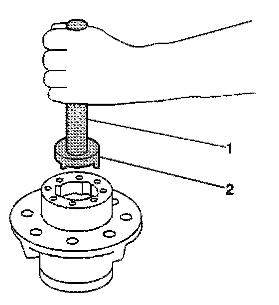
Note: Ensure that the outer bearing assembly rotates freely in the hub
9. Using the J 24426 installer (2) and the J 8092 handle (1), turn the rear axle hub over and seat the outer bearing assembly against the retaining ring.
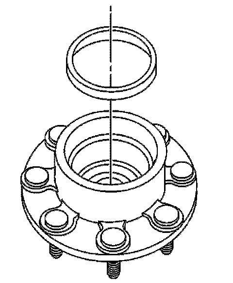
10. Turn the rear axle hub over and install the inner bearing cup.
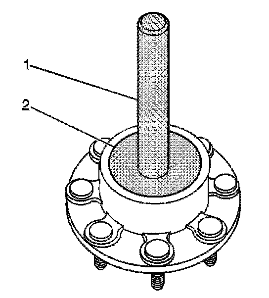
11. Using the J 24427 installer (2) and the J 8092 handle (1), install the inner bearing cup into the wheel hub.
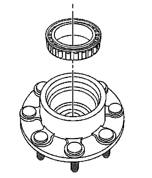
12. Install the inner bearing.
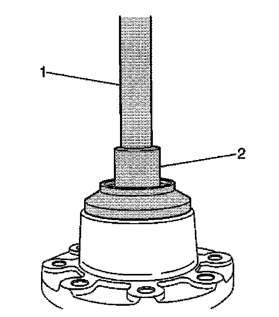
Note: Ensure the seal is fully seated in the hub bore.
13. Using the J 44420 installer (2) and the J 8092 handle (1), install the new oil seal.
14. Apply a light coat of high melting point EP bearing lubricant to the axle housing spindle.
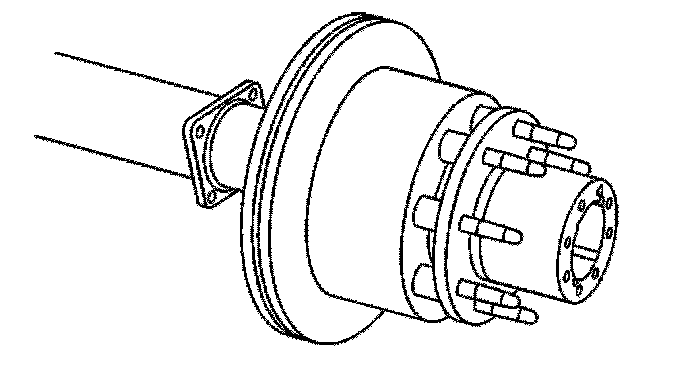
Note: If the rear axle hub assembly does not fully seat itself onto the axle shaft spindle and is removed, the rear axle hub seal must be replaced.
15. Install the rear axle hub.
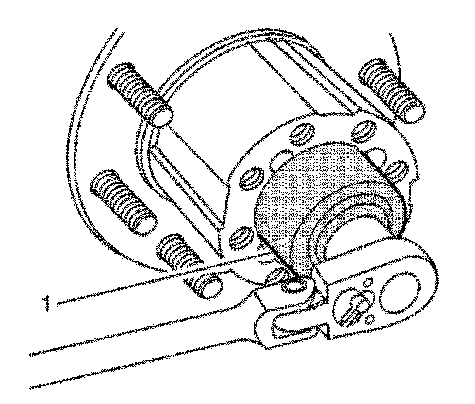
Note: Install the rear wheel bearing adjuster nut by hand.
16. Using the J 2222-C wrench , adjust the rear wheel bearings. Refer to Wheel Bearing Adjustment Adjustments.
17. Install the rear axle shaft. Refer to Rear Axle Shaft and/or Gasket Replacement Service and Repair.
18. Install the brake caliper bracket. Refer to Rear Brake Caliper Bracket Replacement Removal and Replacement.
19. Install the tire and wheel assembly.
20. Inspect and add axle lubricant to the axle housing, if necessary. Refer to Rear Axle Lubricant Level Inspection Procedures.
21. Remove the supports and lower the vehicle.