Allison - Automatic Transmission
Range Selector Lever Cable Replacement
Removal Procedure
1. Position the steering column shift lever to the park position.
2. Raise and support the vehicle. Refer to Lifting and Jacking the Vehicle .
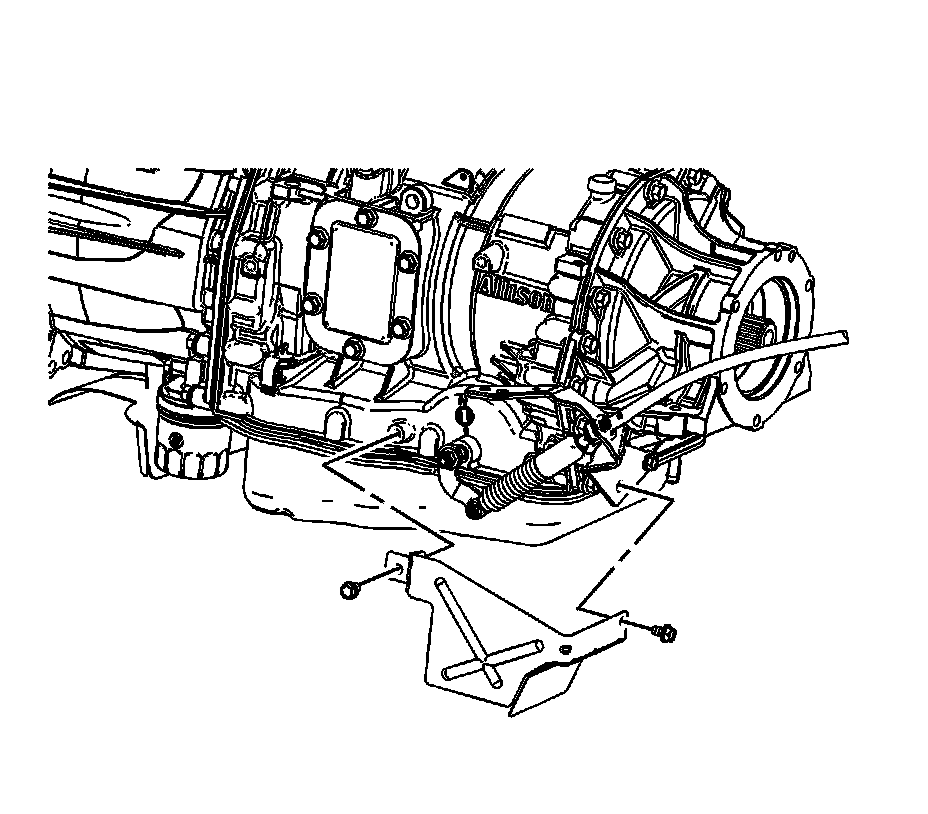
3. Remove the range selector cable heat shield bolts.
4. Remove the range selector cable heat shield.
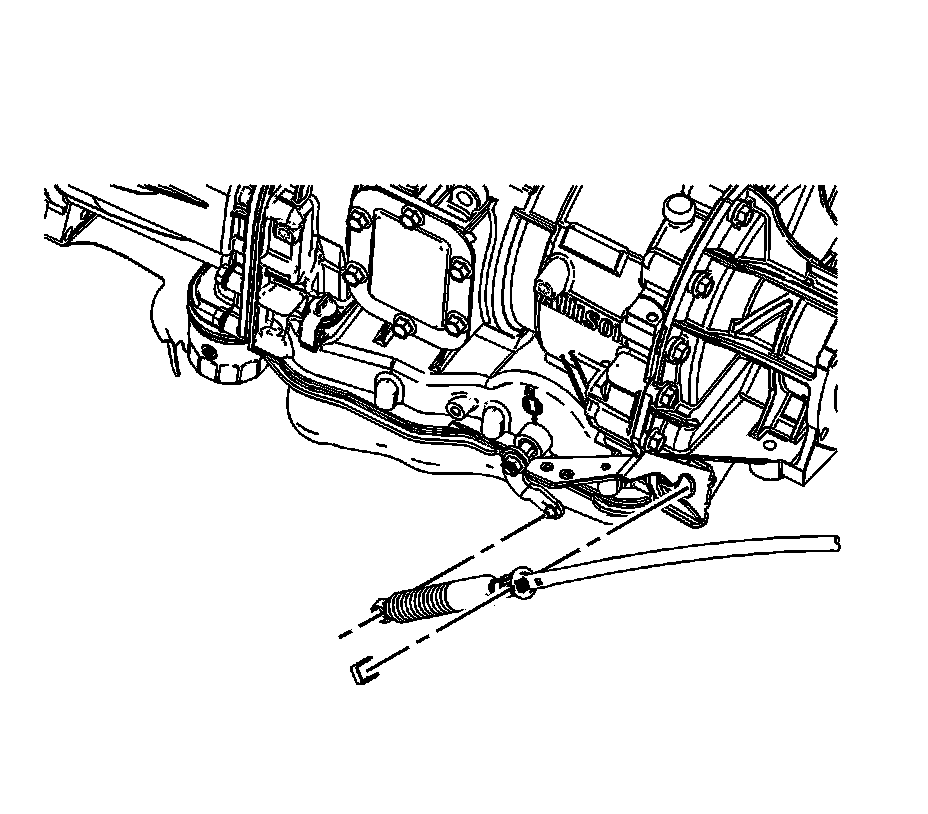
5. Ensure the transmission manual shaft is positioned in mechanical park.
6. Remove the range selector cable end from the transmission range selector lever stud.
7. Remove the retainer securing the range selector cable to the bracket.
8. Depress the tangs and remove the cable from the range selector cable bracket.
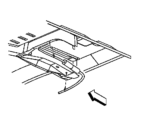
9. Remove the cable clips from the floor panel reinforcement.
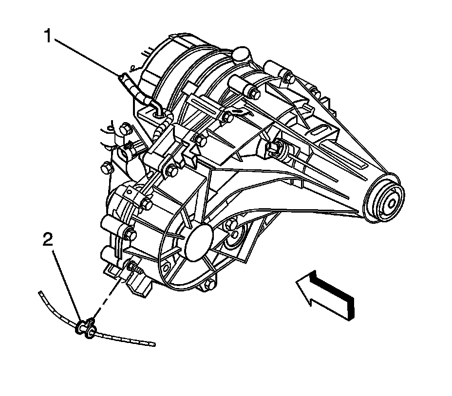
10. Remove the cable clips (2) from the transfer case, if equipped.
11. Lower the vehicle.
12. Ensure that the steering column shift lever is still in the park position.
13. Pull back the carpet and insulation around the driver's area.
14. Remove the instrument panel knee bolster. Refer to Knee Bolster Replacement (with RPO SLT) Knee Bolster Replacement (without RPO SLT) .
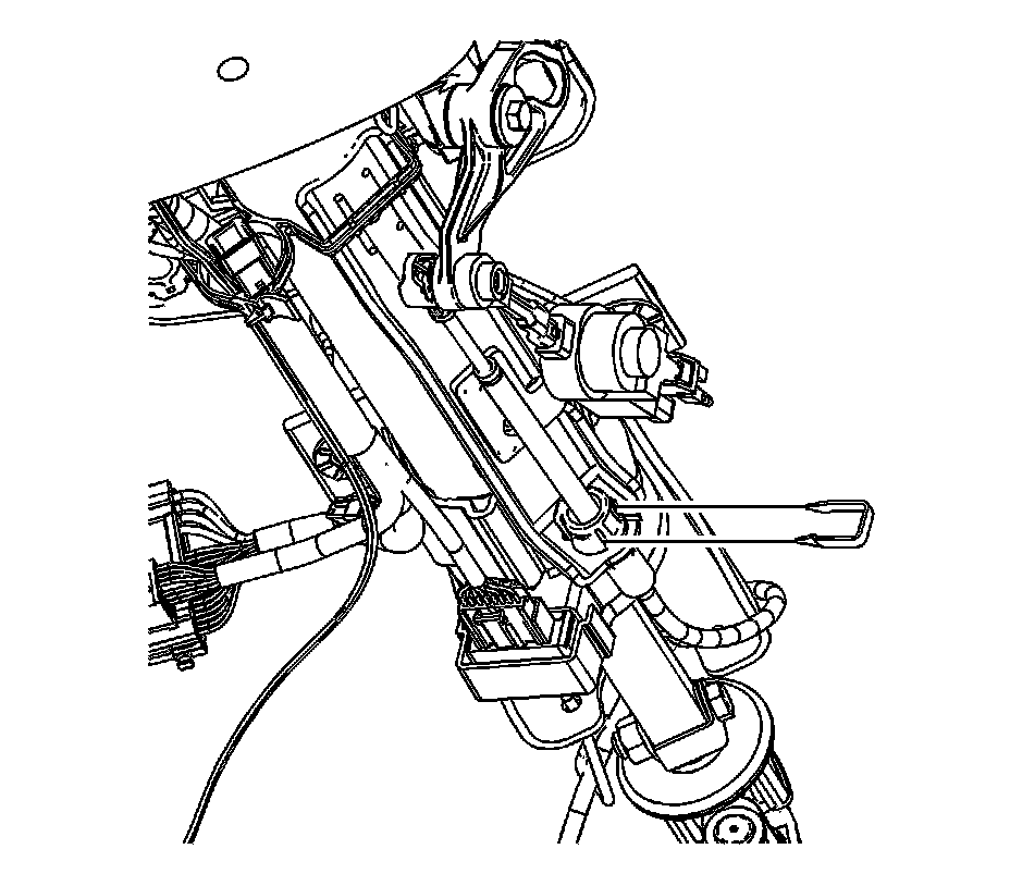
15. Remove the retainer securing the cable to the steering column.
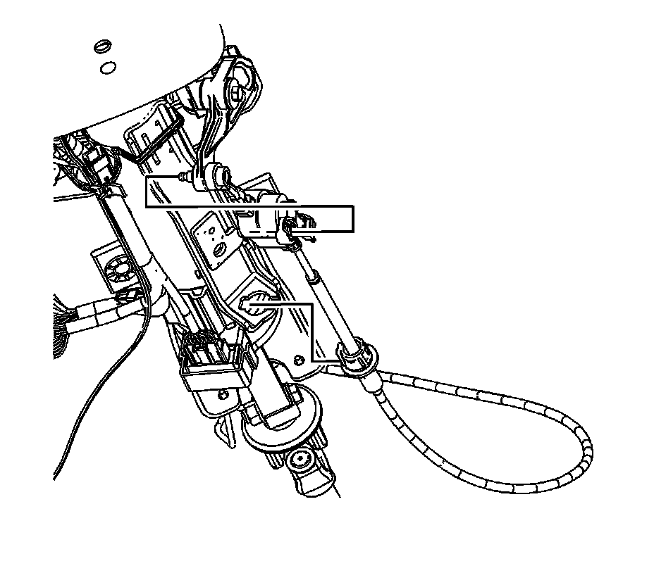
16. Remove the cable end from the steering column ball stud.
17. Depress the tangs and remove the cable from the steering column bracket.
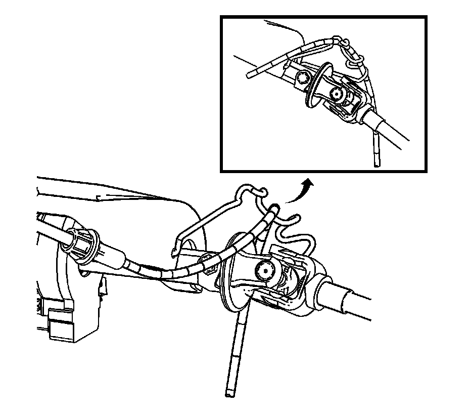
Important: Avoid unnecessary twisting/bending of the range selector cable when removing the cable from the support.
18. Remove the range selector cable from the support.
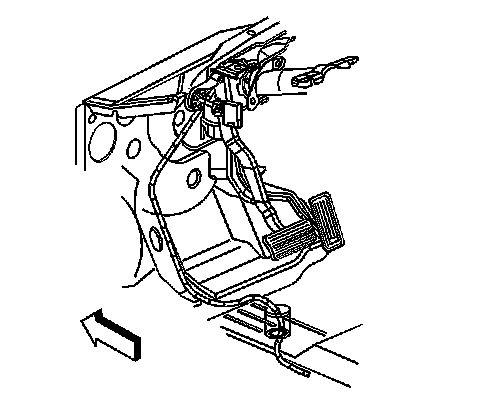
19. Remove the cable grommet from the floor panel.
20. Remove the cable from the vehicle.
Installation Procedure
1. Install the cable to the vehicle.
2. Install the cable grommet to the floor panel.
Important: Avoid unnecessary twisting/bending of the range selector cable when installing the cable to the support.
3. Install the range selector cable to the support.
4. Ensure that the transmission manual shaft lever is in the mechanical park position.
5. Install the cable to the steering column bracket.
6. Ensure the tangs fully seat (snap) into the steering column bracket.
7. Install the cable end to the steering column ball stud.
8. Install the retainer securing the cable to the steering column.
9. Position the carpet and insulation around the driver's area.
10. Install the instrument panel knee bolster. Refer to Knee Bolster Replacement (with RPO SLT) Knee Bolster Replacement (without RPO SLT) .
11. Raise and support the vehicle. Refer to Lifting and Jacking the Vehicle .
12. Install the cable clips (2) to the transfer case, if equipped.
13. Install the cable clips to the floor panel reinforcement.
14. Ensure the transmission manual shaft is positioned in mechanical park.
15. Install the range selector cable to the range selector cable bracket.
16. Install the retainer securing the range selector cable to the bracket.
17. Install the range selector cable end to the transmission range selector lever stud.
18. Install the range selector cable heat shield.
Notice: Refer to Fastener Notice .
Important: Install bolts by hand then mechanically tighten the front bolt first and the rear bolt last. Failure to tighten the bolts in the specified order will result in misalignment of the heat shield.
19. Install the range selector cable heat shield bolts.
Tighten the front bolt to 25 N.m (18 lb ft).
Tighten the rear bolt to 25 N.m (18 lb ft).
20. Lower the vehicle.
21. Test the transmission for proper shift operation.
22. If all of the gear positions cannot be achieved, adjust the cable. Refer to Range Selector Lever Cable Adjustment (Adjustments) .