Camshaft Position Actuator Solenoid Valve Replacement
Camshaft Position Actuator Solenoid Valve Replacement
Special Tools
* J 42386-A Flywheel Holding Tool
* J 45059 Angle Meter
Removal Procedure
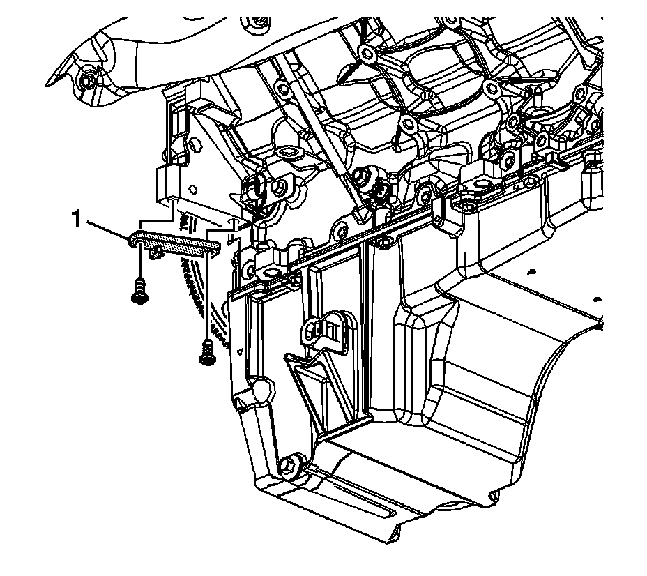
Notice: Refer to Fastener Notice .
1. Install the J 42386-A (1) and bolts. Use 1 M10 - 1.5 x 120 mm and 1 M10 - 1.5 x 45 mm bolt for proper tool operation.
Tighten the J 42386-A bolts to 50 N.m (37 lb ft).
2. Remove the camshaft position (CMP) actuator magnet. Refer to Camshaft Position Actuator Magnet Replacement (Camshaft Position Actuator Magnet Replacement) .

Caution: Refer to Camshaft Position Actuator Removal and Installation Caution .
3. Remove the CMP actuator solenoid valve (234).
4. Discard the solenoid valve.
Installation Procedure
1. Install a NEW CMP actuator solenoid valve (234).
With the CMP actuator properly positioned onto the camshaft, the CMP actuator solenoid valve can be threaded completely into the camshaft using light hand pressure. Tighten by hand until snug.

2. Tighten the CMP actuator solenoid valve.
1. Tighten the CMP actuator solenoid valve a first pass to 65 N.m (48 lb ft).
2. Tighten the CMP actuator solenoid valve a final pass an additional 90 degrees using the .
3. Remove the J 42386-A (1).
4. Install the CMP actuator magnet. Refer to Camshaft Position Actuator Magnet Replacement (Camshaft Position Actuator Magnet Replacement) .